Method for producing crankshaft support

A support device and crankshaft technology, applied in crankshaft bearings, manufacturing tools, casting molding equipment, etc., can solve the problems of rigid FRM exposure, prefabricated parts broken, poor processing performance, etc., and achieve the effect of preventing displacement

Inactive Publication Date: 2004-01-21
SUZUKI MOTOR CO LTD
View PDF2 Cites 8 Cited by
  • Summary
  • Abstract
  • Description
  • Claims
  • Application Information

AI Technical Summary

Problems solved by technology

[0010] In addition, this displacement may result in the fragmentation of the preform under the impact of th

Method used


Image

  • Method for producing crankshaft support
  • Method for producing crankshaft support
  • Method for producing crankshaft support

Examples


Example Embodiment

[0018] Referring now to the accompanying drawings, the present invention will be described in detail.

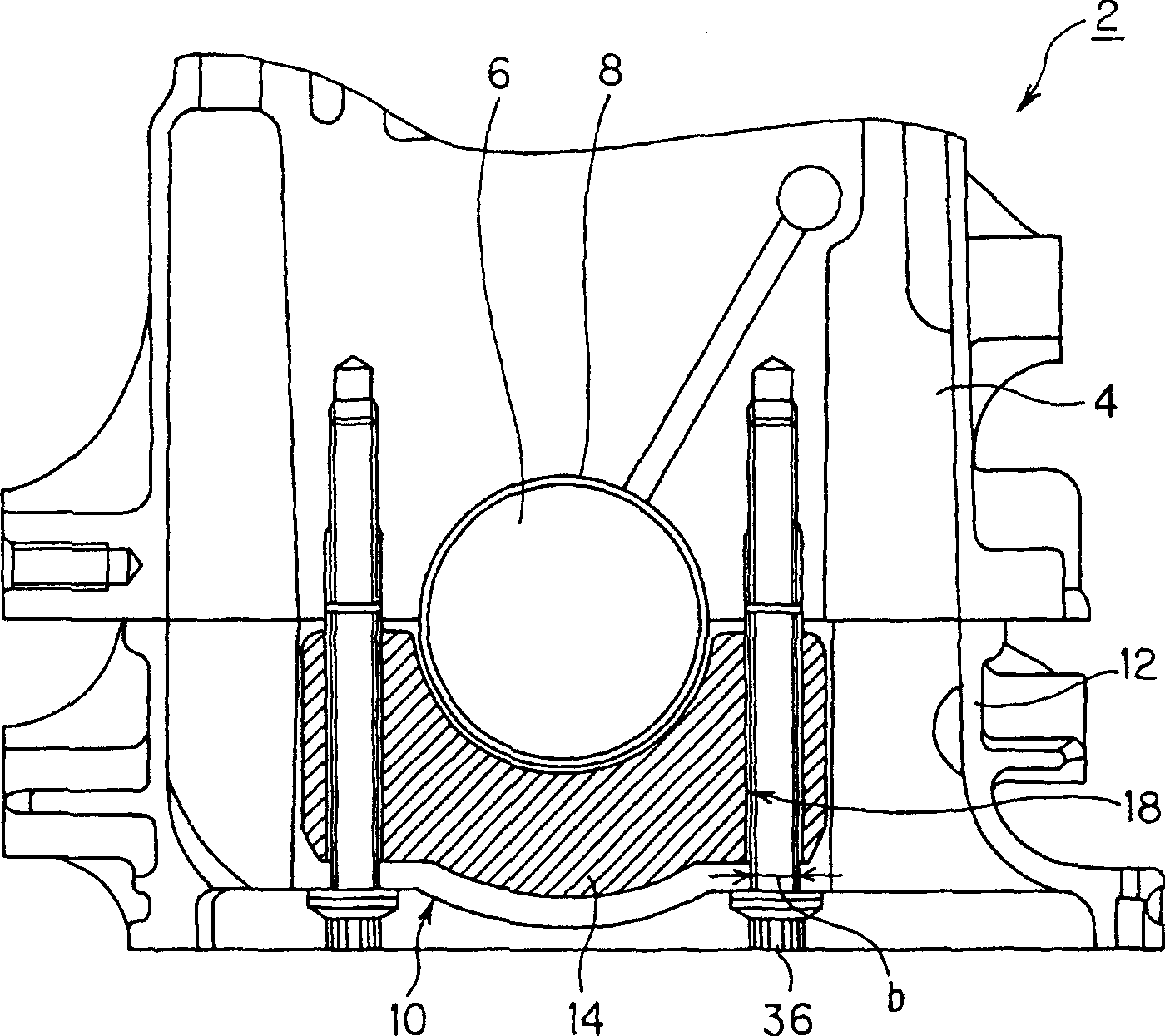
[0019] figure 1 and 2 Embodiments of the invention are shown. figure 2 Shown are components of the engine 2 and the cylinder block 4 .

[0020] In the engine 2, a cylinder head (not shown) is mounted on top of a cylinder block 4 having cylinders (not shown) inside. Below the cylinder block 4 , the crankcase 12 has a crankshaft support comprising a bearing holder 10 on which is supported a bearing 8 for a crankshaft 6 which is arranged between the cylinder block 4 and the crankcase. An oil pan (not shown) is attached to the bottom of the crankcase 12 .

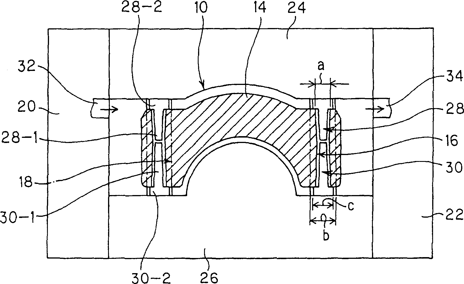
[0021] The bearing holding part 10 is preferably cast from an aluminum alloy and has a preform 14 cast inside it. The preform 14 is typically constructed from fired alumina fibers.

[0022] In the bearing retaining portion 10, pin holes 16 having an inner diameter "a" extend outwardly through the preform 14 and receive...


PUM


Abstract

A method for manufacturing a crankshaft supporter having a bearing holding section that holds a bearing for supporting a crankshaft, and that is cast in aluminum alloy with a preform cast inside, the preform having a through hole extending therethrough. Provided are a core pin to process the through hole, and a pin hole shaped in the preform to accommodate the core pin. The core pin includes a pin insert section having an outer diameter less than inner diameter of the preform pin hole, and a head section having an outer diameter greater than the inner diameter of the preform pin hole. The pin hole insert section is inserted into the pin hole to contact the head section with an outer surface of the preform for securement inside a mold for casting. The core pin is removed during subsequent cutting of a larger diameter hole through the cast bearing holding section.

Description

technical field [0001] The present invention relates to a method of manufacturing a crankshaft bearing, particularly a method of casting a crankshaft bearing in which a preform is cast in a bearing holding portion and the preform is prevented from moving by using a core pin. Background technique [0002] Some vehicles are provided with an internal combustion engine having a cylinder head mounted on a block defining one or more cylinders, a lower crankcase located below the block for supporting the crankshaft with the block, and The lower crankcase has a crankshaft support with a bearing retainer inside; and an oil pan attached to the bottom of the lower crankcase. [0003] One example of a method of manufacturing a crankshaft bearing is disclosed in Japanese Patent Laid-Open Document H06-142834. According to the manufacturing method disclosed therein, support grooves are formed on both inner sides of the water jacket core. The first core pin supports both sides and the upp...

Claims


Application Information

Patent Timeline
IPC IPC(8): F02F7/00B22C9/10B22C9/24B22D19/00B22D19/08F16C9/02
CPCB22D19/08F05C2251/042Y10T29/49286
Inventor 中村慎
Owner SUZUKI MOTOR CO LTD
Why Eureka
Try Eureka