
Gaseous-based detector for ionizing radiation and method in manufacturing the same

A technology for ionizing radiation and detectors, applied in the field of ionizing radiation detection, can solve problems such as hindering detectors and harmful electronic equipment of detectors

Inactive Publication Date: 2004-01-21
XCOUNTER
View PDF0 Cites 3 Cited by
  • Summary
  • Abstract
  • Description
  • Claims
  • Application Information

AI Technical Summary

Problems solved by technology

[0006] This sparkover hampers the detector for a period of time and is also detrimental to the detector and especially to the electronics therein

Method used


Image

  • Gaseous-based detector for ionizing radiation and method in manufacturing the same
  • Gaseous-based detector for ionizing radiation and method in manufacturing the same
  • Gaseous-based detector for ionizing radiation and method in manufacturing the same

Examples


Embodiment Construction

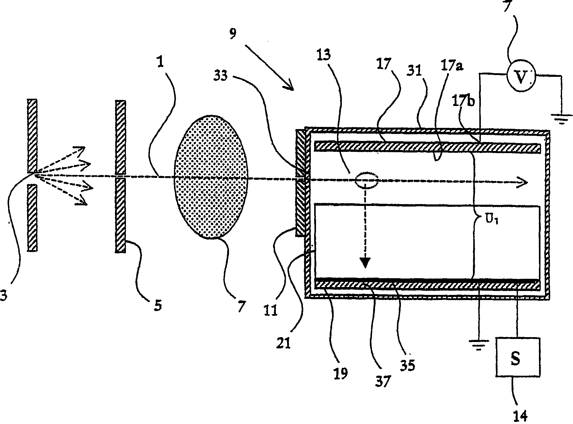
[0020] figure 1 is a cross-sectional view in a plane orthogonal to the plane of a planar fan-shaped X-ray beam 1 of the flat beam radiography apparatus according to the first embodiment of the present invention. The device comprises an X-ray source 3 which, together with a narrow window 5 of a first collimator, generates a planar X-ray beam 1 which illuminates an object 7 to be imaged.

[0021] The beam of rays penetrating the object 7 enters the detector 9 . Alternatively, a slit or second collimator window 11 aligned with the X-ray beam forms the entrance of the X-ray beam 1 into the detector 9 .

[0022] The detector 9 is positioned such that the X-ray photons can enter from the side between the cathode assembly 17 and the anode assembly 19, between which there is a space 13 capable of being charged with an ionized gas or gas mixture. A voltage U can be applied between the cathode 17 and the anode 19 by means of the high voltage direct current source 7 1 , so that electr...


PUM


Abstract

A detector (9) for detection of ionizing radiation comprises a cathode (17, 41); an anode (19); an ionizable gas arranged between these electrodes; a radiation entrance (33) arranged such that ionizing radiation (1) can enter and ionize the ionizable gas; and a read-out arrangement. A voltage across the electrodes causes electrons created during ionization of the gas to drift towards the anode, where the read-out arrangement (19) detects them. To reduce the risk of occurrence of sparks, and / or to reduce the energy in occurring sparks, the cathode has at least the surface layer facing the anode made of a material having a resistivity of at least 5x10<-8> OMEGA m.

Description

technical field [0001] The present invention relates to gas-based detection of ionizing radiation. Background technique [0002] In general, gas-based ionizing radiation detectors are very attractive because they are inexpensive to produce and can utilize gas multiplication to significantly amplify the signal amplitude. [0003] A typical gas-based ionizing radiation detector includes a flat cathode and anode assembly, respectively, and an ionizing gas disposed between the cathode and anode. The detector is arranged such that a beam of radiation emitted by the radiation source can enter the detector to ionize the ionized gas. Additionally, a voltage is typically applied to move electrons generated during ionization of the ionized gas toward the anode. The voltage of the detector electrodes and their configuration can be adjusted such that electron multiplication is achieved, thereby inducing an enhanced charge at the anode assembly. A readout assembly, typically comprisin...

Claims


Application Information

Patent Timeline
Patent Type & Authority Applications(China)
IPC IPC(8): G01T1/18G01TG01T1/00G01T1/185H01J47/02
CPCG01T1/00H01J47/02G01T1/18G01T1/185H01J47/026
Inventor T·弗兰克J·兰塔宁C·乌尔贝里
Owner XCOUNTER
Learn More