Hollow member ,manufacturing method, thereof, fluid distribution system using hollow member, and forming apparatus of hollow member

A technology for fluid distribution and forming equipment, applied in the direction of manufacturing tools, mechanical equipment, welding equipment, etc., can solve the problems of inability to reduce manufacturing costs, poor appearance, and larger equipment.

Inactive Publication Date: 2004-02-04
TOYOTA JIDOSHA KK
View PDF3 Cites 19 Cited by
  • Summary
  • Abstract
  • Description
  • Claims
  • Application Information

AI Technical Summary

Problems solved by technology

In addition, when such a step is formed outside the hollow member, there is also a problem that the appearance of the product is not good
[0013] On the other hand, in the case of forming a hollow material by joining material plates to form a panel, and bending the panel and joining opposite sides, a flattening seam welder for joining the panels and another for connecting Flatten seam welding machine on the opposite side of the curved plate, there is a problem that the equipment for forming the hollow material becomes larger and the manufacturing cost cannot be reduced

Method used


Image

  • Hollow member ,manufacturing method, thereof, fluid distribution system using hollow member, and forming apparatus of hollow member
  • Hollow member ,manufacturing method, thereof, fluid distribution system using hollow member, and forming apparatus of hollow member
  • Hollow member ,manufacturing method, thereof, fluid distribution system using hollow member, and forming apparatus of hollow member

Examples


Embodiment Construction

[0085] In the following description and drawings, the invention will be explained in detail on the basis of a preferred embodiment.

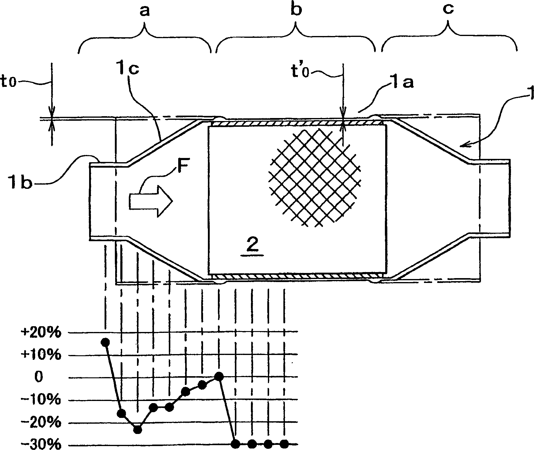
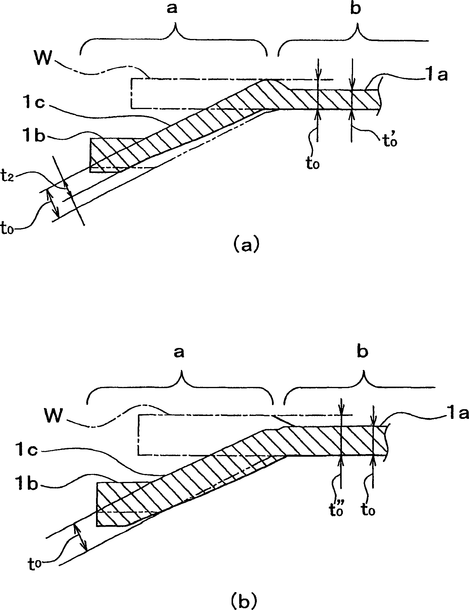
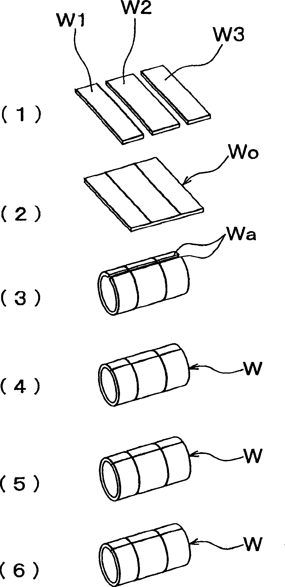
[0086] Embodiments of the present invention will be described in detail below with reference to the accompanying drawings, wherein the fluid distribution system is an exhaust system for purifying exhaust gas of a combustion engine such as an internal combustion engine, and the hollow member is a catalytic converter for fixing a catalyst carrier inside Catalyst container 1. Here, the same parts as in the conventional art are denoted by the same reference numerals, and detailed description thereof will be omitted. In this specification, the cylindrical part in this method is called "hollow material", and after the spinning process for making the hollow material into a predetermined shape is completed, the changed cylindrical part whose cross-sectional shape is drawn is It is called "hollow member".

[0087] figure 1 A sectional view showing a ...


PUM


Abstract

Individual plate members (W1, W2, W3, W4, W5) that are different in plate thickness or material are joined together by mush seam welding to form hollow material (W, W'), and the rigidity is controlled in individual parts. By spinning the rigidity material (W, W'), a junction (1b) and a cone (1c) are formed in an optimum shape, and a hollow member (1) is manufactured. Thus, the hollow member (1) smooth in juntion and high in welding strength is obtained in spite of thin plate material. When this hollow member (1) is used in a catalyst container, the sealing performance is excellent without being accompanied by an increase in radiant noise or an increase in weight.

Description

technical field [0001] The present invention relates to a hollow member, a method of manufacturing the same, a fluid distribution system using the same, and an apparatus for forming a hollow material. Background technique [0002] Fluid dispensing systems for dispensing specific gases and changing their composition during dispensing are widely used in various technical fields. For example, in a combustion engine such as an internal combustion engine, the exhaust pipe for expelling exhaust gases into the atmosphere includes a fluid distribution system for exhaust gas purification. [0003] An exhaust pipe is connected to a catalytic converter to remove harmful substances contained in exhaust gas. The catalytic converter is provided with a catalyst carrier in a catalyst container. Such as Figure 26 As shown in (d), in the catalyst container 101, generally, the catalyst carrier mounting portion 101a is formed at the center thereof, and the tubular joint portion 101b is forme...

Claims


Application Information

Patent Timeline
Patent Type & Authority Applications(China)
IPC IPC(8): B21D22/14B21C37/08B21C37/15B21D22/18B21D41/04B21D51/18B21D53/84B21D53/88B23K11/00B23K11/06B23K11/20F01N3/28
CPCB21D53/88F01N2450/02B23K11/0026B23K2201/006F01N3/2842B21D22/18B21C37/15B23K2201/04B21C37/0815B23K11/063B21C37/065B23K11/065B21C37/0803B23K2101/006B23K2101/04Y10T29/49345Y10T29/49826B21D22/14B21D51/10B21K11/00
Inventor 梅田正浩吉本健次石津诚二大沼正史大山刚
Owner TOYOTA JIDOSHA KK
Why Eureka
Try Eureka