Power converter and power generator

A power generation device and power conversion technology, which is applied in circuit devices, output power conversion devices, adjustment of electrical variables, etc.

Inactive Publication Date: 2004-02-11
CANON KK
View PDF3 Cites 100 Cited by
  • Summary
  • Abstract
  • Description
  • Claims
  • Application Information

AI Technical Summary

Problems solved by technology

However, for unstable power sources, it is unknown which power converter has high operating efficiency and can construct a low-cost power generation device

Method used


Image

  • Power converter and power generator
  • Power converter and power generator
  • Power converter and power generator

Examples


Embodiment 1

[0089] Embodiment 1 is an example in which a thin-film solar cell in which amorphous and microcrystalline layers are laminated is used as the solar cell 7 . In addition, since the structure or manufacturing method of the laminated solar cell and the mounting method of the collecting electrodes are irrelevant to the essence of the present invention, detailed explanations are omitted, and they are disclosed in JP-A-11-243219 or JP-A-8-139439 Bulletin etc.

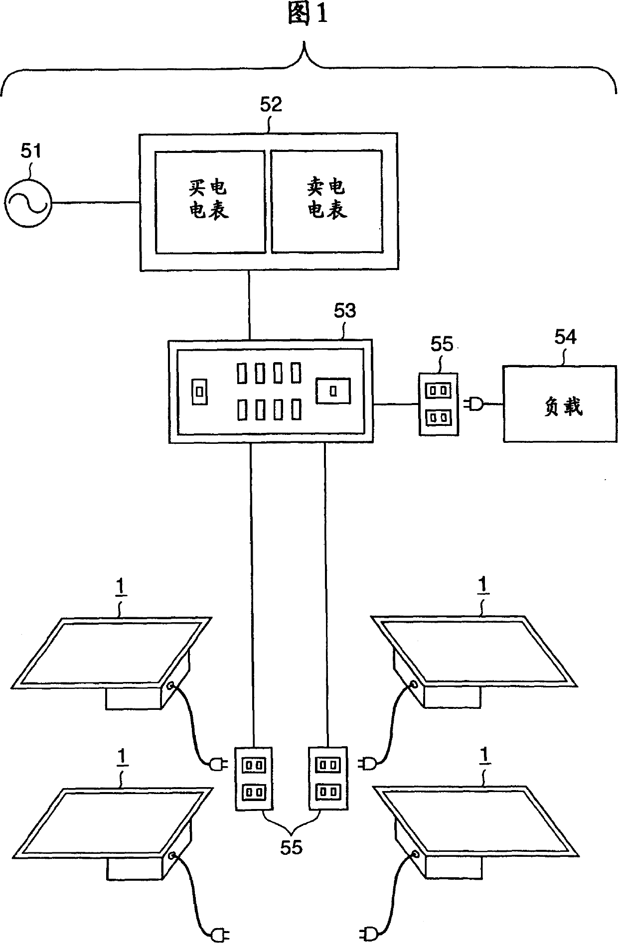
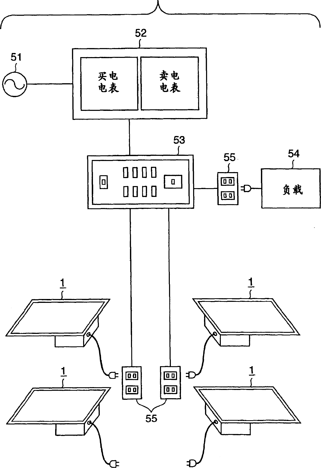
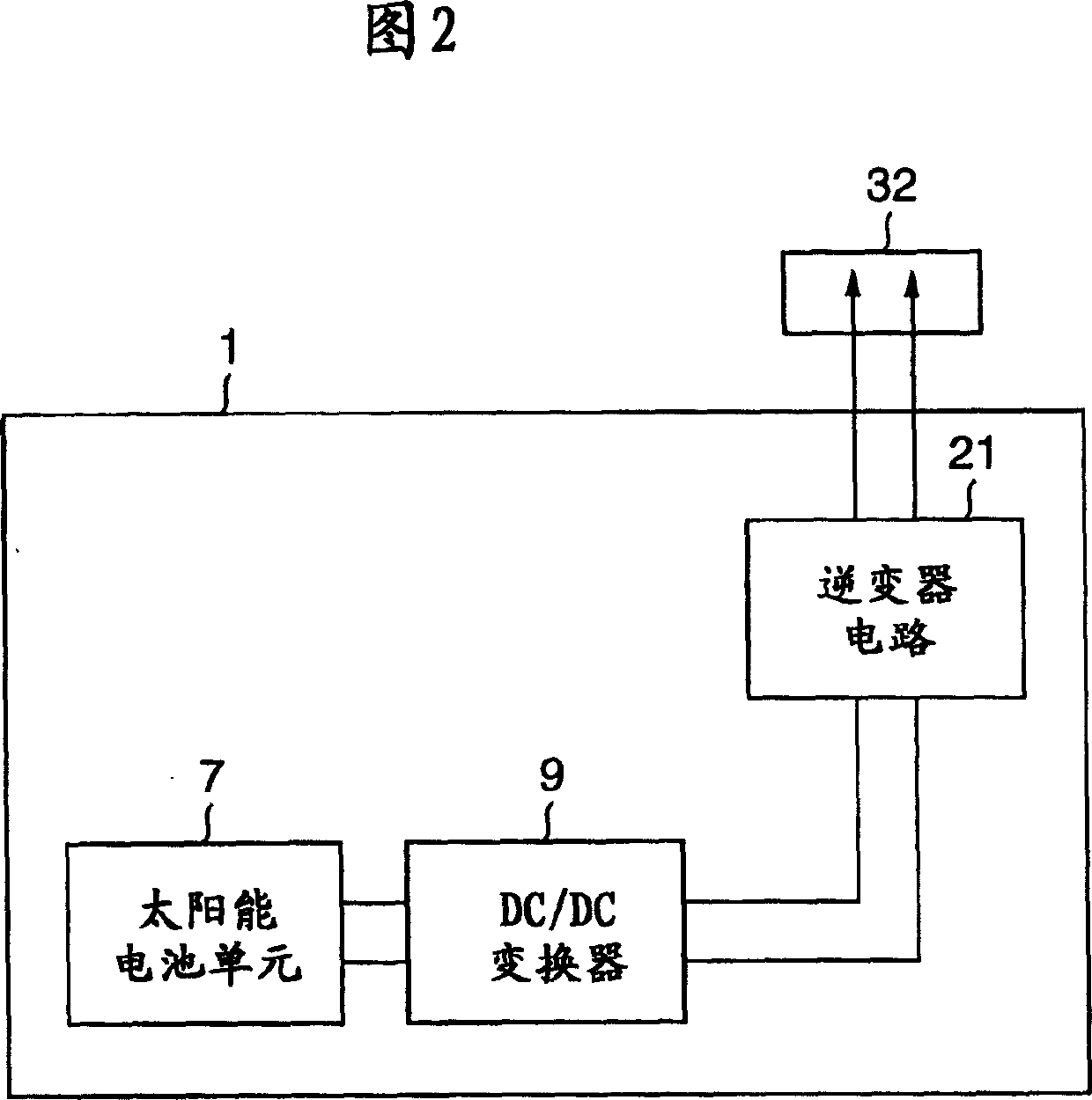
[0090] The single unit performance of the solar battery unit 7 is an output of 1.0V, 15.0A in rated sunlight (spectrum AM1.5, 100mW / cm2, unit temperature 55°C). A DC / DC converter 9 is installed in one solar battery unit 7 to form a power generation device.

[0091] transformer

[0092] If the minimum operating voltage of the solar battery unit 7 is set as 0.8V, then the boost ratio when the 100V system is used as the connection target can be 0.8:140=1:175, and in order to leave a margin, the variable voltage of the transfor...

Embodiment 2

[0105] In the second embodiment, the primary winding of the transformer 15 used in the DC / DC converter 9 is set to three turns. FIG. 21 shows the standard using the transformer 15 in Embodiment 2.

[0106] FIG. 7 is the same as FIG. 6, and plots the relationship between the power conversion efficiency of the DC / DC converter 9 in Embodiment 2 and the input voltage according to different input powers.

[0107] Compared with Example 1, the DC / DC converter 9 of Example 2 roughly shows that the conversion efficiency is good when the sunlight is low (input power is 1 to 8W), and the conversion efficiency is good when the sunlight is high (input power is 9 to 15W). tendency to decrease.

Embodiment 3

[0118] In Example 3, a solar battery cell in which three photoelectric conversion layers including amorphous silicon were laminated was used as the solar battery cell 7 . A method of manufacturing such a solar battery cell is disclosed in JP-A-6-21494 and the like.

[0119] The performance of the solar battery cell 7 is 1.5V, 30W in rated sunlight (spectrum AM1.5, 100mW / cm2, cell temperature 55°C). In addition, the optimum operating point voltage of the solar battery cell 7 varies between 1.2 and 1.8 V according to changes in the environment (sunlight, temperature).

[0120] The DC / DC converter 9 is the same as other embodiments, and is composed of a push-pull circuit, its switching frequency is 40kHz, and the duty ratio is fixed at 50%. Here, since the voltage of the solar cell 7 is different from that of the first embodiment, the transformation ratio of the transformer 15 used is changed.

[0121] transformer

[0122] Since the minimum value of the optimal operating point...


PUM


Abstract

A power converter is installed for each solar cell, and electric power having a low voltage and a relatively large electric current is input to the power converter, thereby reducing as much as possible the wiring work which greatly raises the cost of an electric power generator. For this purpose, a power converter which has a high operating efficiency and by which a low-cost electric power generator can be constructed when an unstable power source such as a solar cell is used is desired. As this power converter, a DC / DC converter is provided which supplies DC power supplied from the solar cell to a transformer by switching the DC power, thereby boosting the output voltage from the solar cell by a few tens of times to a few hundred times. The number of turns of the primary winding of the transformer is set to 2 or 3.

Description

technical field [0001] The present invention relates to a power conversion device and a power generation device, in particular to power conversion using an unstable power source as a power supply source. Background technique [0002] Many power supplies with unstable outputs are known. For example, a fuel cell whose power fluctuates greatly due to temperature, a solar cell whose power fluctuates greatly due to sunlight, and a wind generator whose power fluctuates greatly due to wind force are typical examples of unstable power sources. [0003] These power supplies cannot directly use the power generated by them due to their unstable output. Therefore, a method of connecting these power sources to a commercial power system (hereinafter referred to as a "system") is generally used as a means for supplementing electric power when the output of these power sources is low. For example, in order to connect a solar power generation device to a 100V system, connect the solar cell...

Claims


Application Information

Patent Timeline
Patent Type & Authority Applications(China)
IPC IPC(8): G05F1/67H02J3/04H02M3/28H02M7/48H02M7/539
CPCH02M7/538H02M7/53871H02M7/539H02J3/04H02M3/28G05F1/67H02M7/48
Inventor 近藤博志竹原信善
Owner CANON KK
Why Eureka
Try Eureka