

Development device and electronic photographing apparatus
A potential and latent image technology, which can be applied in the equipment, electrorecording technique, electric recording process applying charge pattern, etc. Smudges, etc.
- Summary
- Abstract
- Description
- Claims
- Application Information
AI Technical Summary
Problems solved by technology
Method used
Image

Examples
Embodiment 1
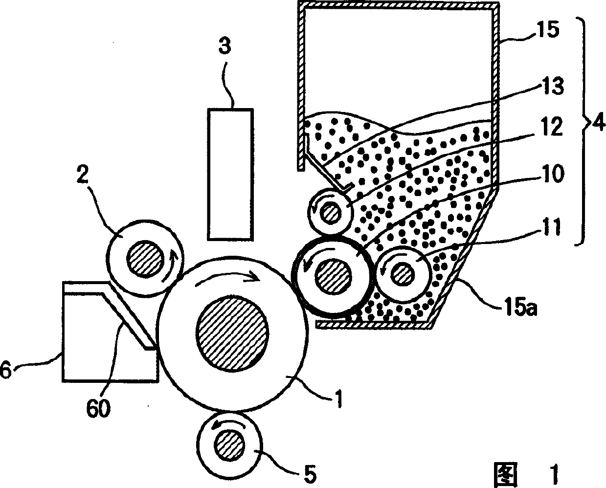
[0029] FIG. 1 is a cross-sectional view of a main part of an electrophotographic apparatus including a developing device according to Embodiment 1. FIG. The electrophotographic apparatus is an electrophotographic apparatus of a non-magnetic one-component developing type. The electrophotographic apparatus includes a photosensitive drum 1 (hereinafter referred to as a drum 1) as a latent image generating member. A photosensitive layer is formed on the outer peripheral surface of the drum 1 . When the photosensitive layer is not exposed to light, the photosensitive layer is insulating, and when exposed to light, the photosensitive layer becomes conductive, thereby releasing charges therefrom. The drum 1 rotates in one direction (ie clockwise in Figure 1). A charging roller 2 , a light emitting diode (LED) head 3 , a developing device 4 , a transfer roller 5 and a cleaning unit 6 are provided along the circumference of the drum 1 in accordance with the rotation direction of the ...
Embodiment 2
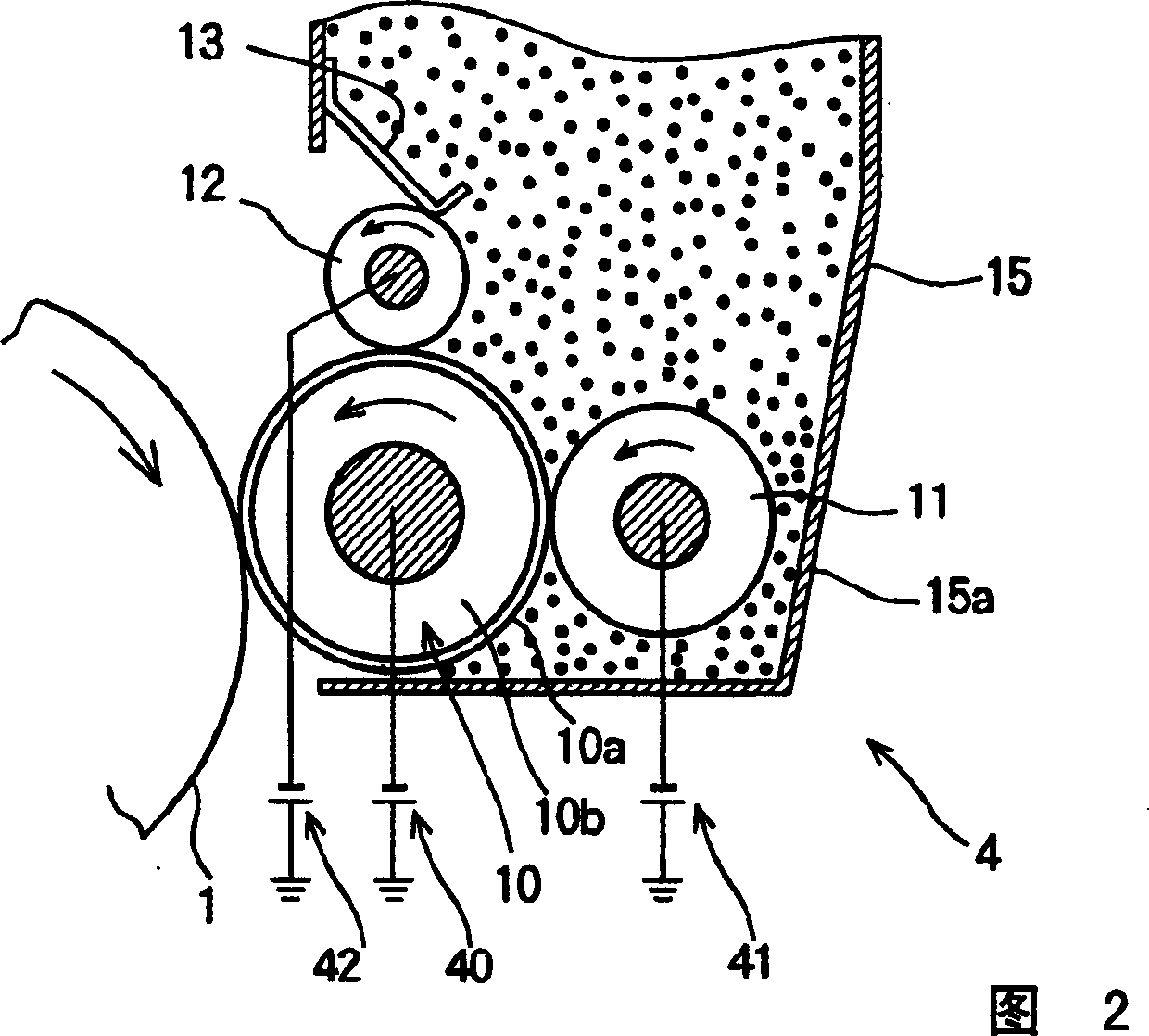
[0062] FIG. 7 is an enlarged view of a developing device 4A according to Embodiment 2 of the present invention. In addition to the components of the developing device ( FIG. 2 ) of Embodiment 1, the developing device 4A has an auxiliary supply roller (a kind of auxiliary supply member) 16 adjacent to the toner layer forming roller 12 . The structure of the fixing device 4A is the same as that of the fixing device 4 of Embodiment 1 except that the auxiliary supply roller 16 is provided. The fixture 4A is attached to the electrophotographic apparatus as described in Embodiment 1 (FIG. 1). The auxiliary supply roller 16 is provided inside the toner container 15 and is in contact with the right side of the outer peripheral surface of the toner layer forming roller 12 shown in FIG. 2 . The auxiliary supply roller 16 has a rotation axis parallel to the toner layer forming roller 12 and rotates in the same direction as the toner layer forming roller 12 . The auxiliary supply roller...
Embodiment 3
[0068] FIG. 8 is an enlarged view of a fixing device 4B according to Embodiment 3 of the present invention. In addition to the components of the fixture 4 ( FIG. 2 ) of Embodiment 1, the fixture 4B has an additional supply roller (an additional supply member) 17 adjacent to the supply roller 11 . The configuration of the fixing device 4B is the same as that of the fixing device 4 ( FIG. 2 ) of Embodiment 1, except that this additional supply roller 17 is provided. The fixing device 4B is attached to the electrophotographic apparatus described in Example 1 (FIG. 1).
[0069] In FIG. 8 , the additional supply roller 17 is provided inside the toner container 15 and is in contact with the upper side of the outer peripheral surface of the supply roller 11 . The additional supply roller 17 has a rotation axis parallel to the rotation axis of the supply roller 11 and rotates in the same direction as the supply roller 11 . Like the supply roll 11, the additional supply roll 17 is co...
PUM
| Property | Measurement | Unit |
|---|---|---|
| Diameter | aaaaa | aaaaa |
| Static friction coefficient | aaaaa | aaaaa |
Abstract
Description
Claims
Application Information