Laser vibration detestion method and its equipment

A vibration detection and laser technology, which is applied in the direction of measuring devices, measuring ultrasonic/sonic/infrasonic waves, instruments, etc., can solve the problems of inability to obtain the measured amplitude value, low measurement resolution, and inability to obtain displacement, etc., so as to achieve simple debugging and improved Signal-to-noise ratio, easy-to-use effects

Inactive Publication Date: 2004-02-25
TIANJIN UNIV
View PDF0 Cites 25 Cited by
  • Summary
  • Abstract
  • Description
  • Claims
  • Application Information

AI Technical Summary

Problems solved by technology

The calculation method for vibration characteristics such as amplitude is usually that each beat wave in the signal corresponds to a displacement equivalent value, and the measured amplitude is obtained by counting the number of beat waves between two adjacent flipping points. This method cannot obtain displacements smaller than the equivalent value, and its measuremen

Method used


Image

  • Laser vibration detestion method and its equipment
  • Laser vibration detestion method and its equipment
  • Laser vibration detestion method and its equipment

Examples


Embodiment Construction

[0024] The present invention will be further described below in conjunction with the accompanying drawings and examples.

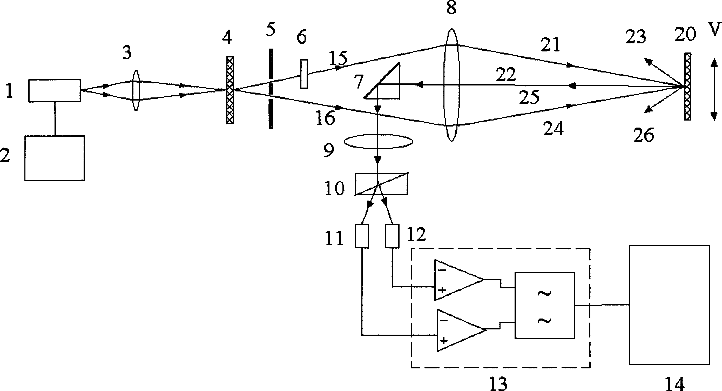
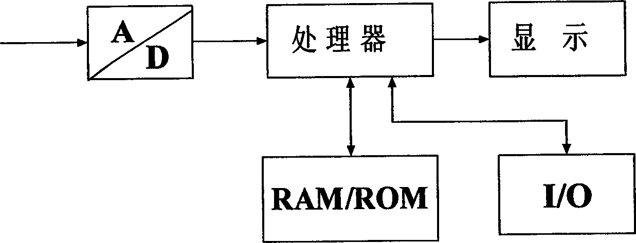
[0025] exist figure 1 Including laser 1, laser power supply 2, focusing lens 3, transmission grating 4, diaphragm 5, λ / 4 wave plate 6, reflecting prism 7, focusing lens 8, frequency mixing element 20, reflecting prism 7, lens 9, splitter Beamer 10, photoelectric receivers 11, 12, amplifying circuit unit 13, signal processing unit 14 and so on. The laser beam emitted by the laser 1 is focused by the lens 3 to the transmission grating 4, and diffraction occurs, and 0-order, ±1-order, ±2-order, ... diffracted lights are emitted, and the aperture 5 filters out +1-order light 15, - Other diffracted light other than the first-order light 16. These two beams of light are transformed by the lens 8 into beams 21 and 24 that are converged to the mixing element 20 and diffracted. The ±1st order lights diffracted by the beam 21 are 22 and 23; Adjusting the position...


PUM


Abstract

The present invention relates to a method and its equipment for accurately measuring and analyzing vibratino of body by utilizing laser technique. The equipment includes laser, laser light source, focusing lens, transmission grating, light diaphragm, lambda/4 wave plate, reflecting prism, focusing lens, lens Wollaston prism, two photoelectric receivers, amplification circuit unit, signal processing unit and frequency mixing element.

Description

technical field [0001] The invention relates to a device for accurately measuring and analyzing the vibration of an object, in particular to a device for accurately measuring and analyzing the vibration by using an optical measurement method. Background technique [0002] The currently disclosed sensors used in the field of vibration and acceleration detection include electromagnetic sensors, piezoelectric sensors, and optical sensors. The common defect of electromagnetic sensors and piezoelectric sensors is the contact measurement method, which needs to be connected with the measured object, which will affect the measured vibration and make the measurement inaccurate. In addition, the electromagnetic sensor has relatively serious nonlinearity, and the dynamic range of measurement is small, while the low-frequency response of the piezoelectric sensor is relatively poor. [0003] Optical sensors are non-contact measurement methods, usually in two typ...

Claims


Application Information

Patent Timeline
IPC IPC(8): G01H9/00
Inventor 蒋诚志杜振辉高华谢艳贺顺忠陶知非李淑清
Owner TIANJIN UNIV
Why Eureka
Try Eureka