Packaging mould with electrostatic discharge protection

A technology for electrostatic discharge protection and electrostatic charge, which is applied in the manufacture of circuits, electrical components, semiconductors/solid-state devices, etc., and can solve problems such as static electricity residue and chip damage

Inactive Publication Date: 2004-03-03
ADVANCED SEMICON ENG INC
View PDF0 Cites 3 Cited by
  • Summary
  • Abstract
  • Description
  • Claims
  • Application Information

AI Technical Summary

Problems solved by technology

[0004] refer to Figure 1b and Figure 1c , use movable thimble pins 131, 132 to push the package substrate 12 out of the groove 11. Since the ejection time is quite short, after the package substrate 12 is completely separated from the groove 11, there may still be static electricity remaining in the package. The substrate 12 is not completely guided out by the inner wall 111 of the groove 11 and the positioning columns 112, 113, so it is still possible that the static electricity generated when the mold is released may damage the chip on the packaging substrate.

Method used


Image

  • Packaging mould with electrostatic discharge protection
  • Packaging mould with electrostatic discharge protection
  • Packaging mould with electrostatic discharge protection

Examples


Embodiment Construction

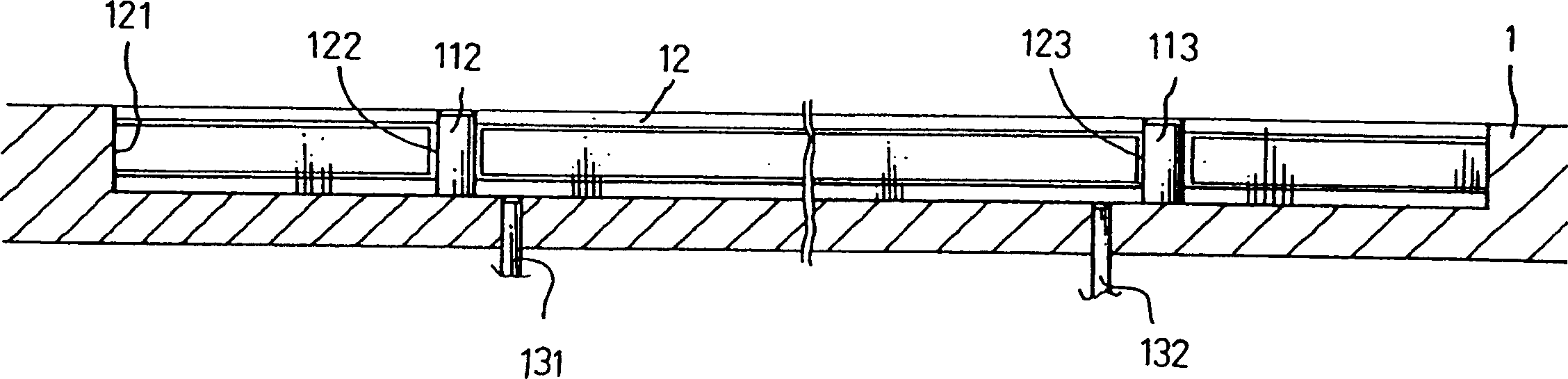
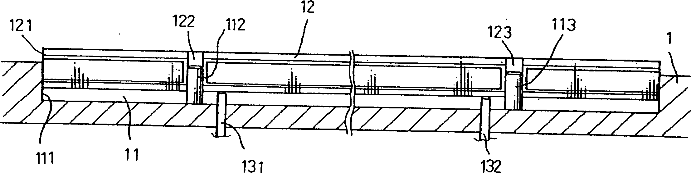
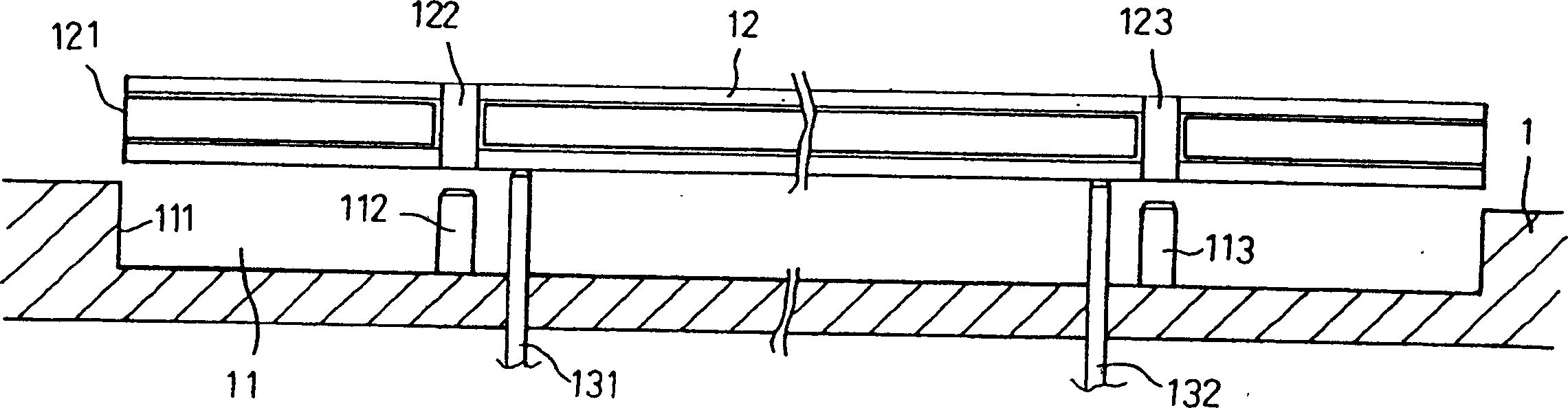
[0012] figure 2 Packaging mold 2 showing the ESD protection of the present invention. The packaging mold 2 includes at least one groove 21 , and each groove 21 is used for accommodating a packaging substrate 22 . The groove 21 has an inner wall 211 . The inner sidewall 211 of the groove 21 is in electrical contact with the outer sidewall 221 of the packaging substrate 22 . The height of the outer wall 221 of the package substrate 22 is a first height H1, and the height of the inner wall 211 of the groove 21 is a second height H2, and the second height H2 is greater than the first height H1.

[0013] The groove 21 also has a plurality of positioning columns 212 , 213 , etc., for passing through the positioning holes 222 , 223 of the packaging substrate 22 , so that the packaging substrate 22 is positioned in the groove 21 . The positioning holes 222 , 223 of the package substrate 22 are in electrical contact with the positioning posts 212 , 213 of the groove 21 . The depth...


PUM


Abstract

The package mould possesses at least one flute to accommodate at least one package base plate. The package base plate possesses outer sidewall with first height, and the flute possesses inner sidewall with second height. The outer wall is connected to the inner wall electrically, and the second height is larger than the first height in order to prolong the contact period between the outer wall and the inner wall when the base plate leaves package mould. Thus, static electricity produced in process of leaving the package mould will be discharged through the assembly. The invention reduces damages caused by electrostatic so as to increase package proporty.

Description

technical field [0001] The invention relates to a packaging mold, in particular, the invention relates to a packaging mold with electrostatic discharge protection. Background technique [0002] Figure 1a to Figure 1c The lower mold 1 of the currently existing packaging mold is shown. The lower mold 1 needs to be molded together with an upper mold (not shown) to package the chip. The conventional packaging mold 1 includes a groove 11 . The groove 11 is used for accommodating a packaging substrate 12 . The groove 11 has an inner sidewall 111 . The inner sidewall 111 is in contact with the outer sidewall 121 of the packaging substrate 12 , wherein the height of the inner sidewall 111 is about the same as the height of the outer sidewall 121 . Moreover, the groove 11 also has a plurality of positioning posts 112 , 113 etc. for passing through the positioning holes 122 , 123 of the package substrate 12 , so that the package substrate 12 is positioned in the groove 11 . [0...

Claims


Application Information

Patent Timeline
IPC IPC(8): H01L21/56
Inventor 洪志斌蒋荣生
Owner ADVANCED SEMICON ENG INC
Why Eureka
Try Eureka