BUCK convertor containing synchronous rectitication drive circuit

A drive circuit and synchronous rectification technology, which is applied in the conversion equipment with intermediate conversion to AC, DC power input is converted to DC power output, and AC power input is converted to DC power output. Only partially adjustable, etc.

Inactive Publication Date: 2004-03-10
EMERSON NETWORK POWER CO LTD
View PDF1 Cites 28 Cited by
  • Summary
  • Abstract
  • Description
  • Claims
  • Application Information

AI Technical Summary

Problems solved by technology

[0018] The purpose of the present invention is to solve the problem of negative pressure generated by the synchronous rectification BUCK converter in the prior art when it is shut down and the problem that there is a "dead zone" between the synchronous rectifier tubes that cannot be adjusted or can only be partially adjusted, and provides a synchronous BUCK converter of rectification drive circuit

Method used


Image

  • BUCK convertor containing synchronous rectitication drive circuit
  • BUCK convertor containing synchronous rectitication drive circuit
  • BUCK convertor containing synchronous rectitication drive circuit

Examples


Embodiment Construction

[0043] The present invention will be described in further detail below through specific embodiments and in conjunction with the accompanying drawings.

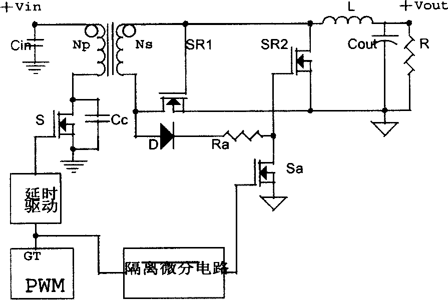
[0044] The drive circuit of the DC-DC converter of the present invention, the main circuit of the converter includes a power MOS tube part, a transformer part, a synchronous rectification part (SR1, SR2), and a filter part, and the drive circuit is composed of an adjustable pulse width Drive pulse signal GT2, an isolated differential circuit, a level comparison and energy conversion circuit MOS transistor Sa, a complementary drive circuit, resistors Ra, Rb, Rc, auxiliary power supply Vcc1 and reference level. The output terminal of the drive pulse signal GT2 with adjustable pulse width is connected to the resistor Ra, the resistor Ra is connected to the input terminal of the isolated differential circuit, and the output terminal of the isolated differential circuit is connected to the level comparison and energy conversion circ...


PUM


Abstract

The convertor includes input power source, rectifying tube, follow current tube, first drive circuit for driving the rectifying tube and second drive circuit for driving the follow current tube. The said second drive circuit includes second pulse width modulator, reverse isolation differential circuit, electrical level comparison and energy conversion circuit, auxiliary power supply and complement drive circuit connected in sequence. One end of complement drive circuit is connected to gate electrode of the follow current tube, and the other end is connected to ground. When shut-off signal comes, high electrical level output by isolation differential circuit is decreased quickly, and electrical level comparison and energy conversion circuit turns on quickly. The complement drive circuit makes electric charge on grid electrode of synchronous follow current MOS discharge quickly, and makes MOS transistor cut off. Thus, shutting down convertor does not generate negative voltage.

Description

Technical field: [0001] The invention relates to a BUCK converter with a synchronous rectification drive circuit. Background technique: [0002] With the development of information technology, digital chips require the power supply voltage to be lower and lower, and the power supply current to be higher and higher. In order to meet the technical requirements of digital chips for the low-voltage and high-current power supply, the synchronous rectification technology used in DC-DC converters has higher efficiency than Schottky rectification technology and has been adopted in DC-DC converter rectification technology. broadly used. The so-called synchronous rectification technology generally uses MOSFET transistors capable of bidirectional conduction instead of Schottky diodes to realize DC-DC converter rectification. Drive it drive three ways. [0003] The self-driving drive mode is widely used in the topology of the main circuit of the DC-DC converter because the circuit is...

Claims


Application Information

Patent Timeline
Patent Type & Authority Applications(China)
IPC IPC(8): H02M3/28H02M3/335H02M7/217
Inventor 雷兴华
Owner EMERSON NETWORK POWER CO LTD
Why Eureka
Try Eureka