Wire tension exerting device for coil winder exerting method thereof

A technology of applying device and winding machine, which is applied in the direction of coil manufacturing, transportation and packaging, and delivery of filamentous materials, etc., which can solve problems such as troublesome, limited wire tension setting range, complex structure, etc.

Inactive Publication Date: 2004-03-17
NITTOKU ENG CO LTD
View PDF2 Cites 14 Cited by
  • Summary
  • Abstract
  • Description
  • Claims
  • Application Information

AI Technical Summary

Problems solved by technology

[0004] However, in the device shown in the above-mentioned prior art 1, it is difficult to set a small tension because the throttle valve for adjusting the cylinder air pressure is used to set the tension value. In addition, in the device shown in the prior art 2, the tension value The setting range of the wire is determined by the stretching range of the spring, so the setting range of the wire tension is limited, and when the setting range of the tension value is to be increased, the spring needs to be replaced, which is very troublesome
[0005] In addition, in the devices shown in such prior art

Method used


Image

  • Wire tension exerting device for coil winder exerting method thereof
  • Wire tension exerting device for coil winder exerting method thereof
  • Wire tension exerting device for coil winder exerting method thereof

Examples


Embodiment Construction

[0026] Below, specific embodiments of the present invention will be described in detail according to the accompanying drawings. However, the dimensions, materials, shapes, and corresponding arrangements of the components described in this embodiment are not intended to limit the scope of the present invention, but are merely examples unless otherwise specified. illustrate.

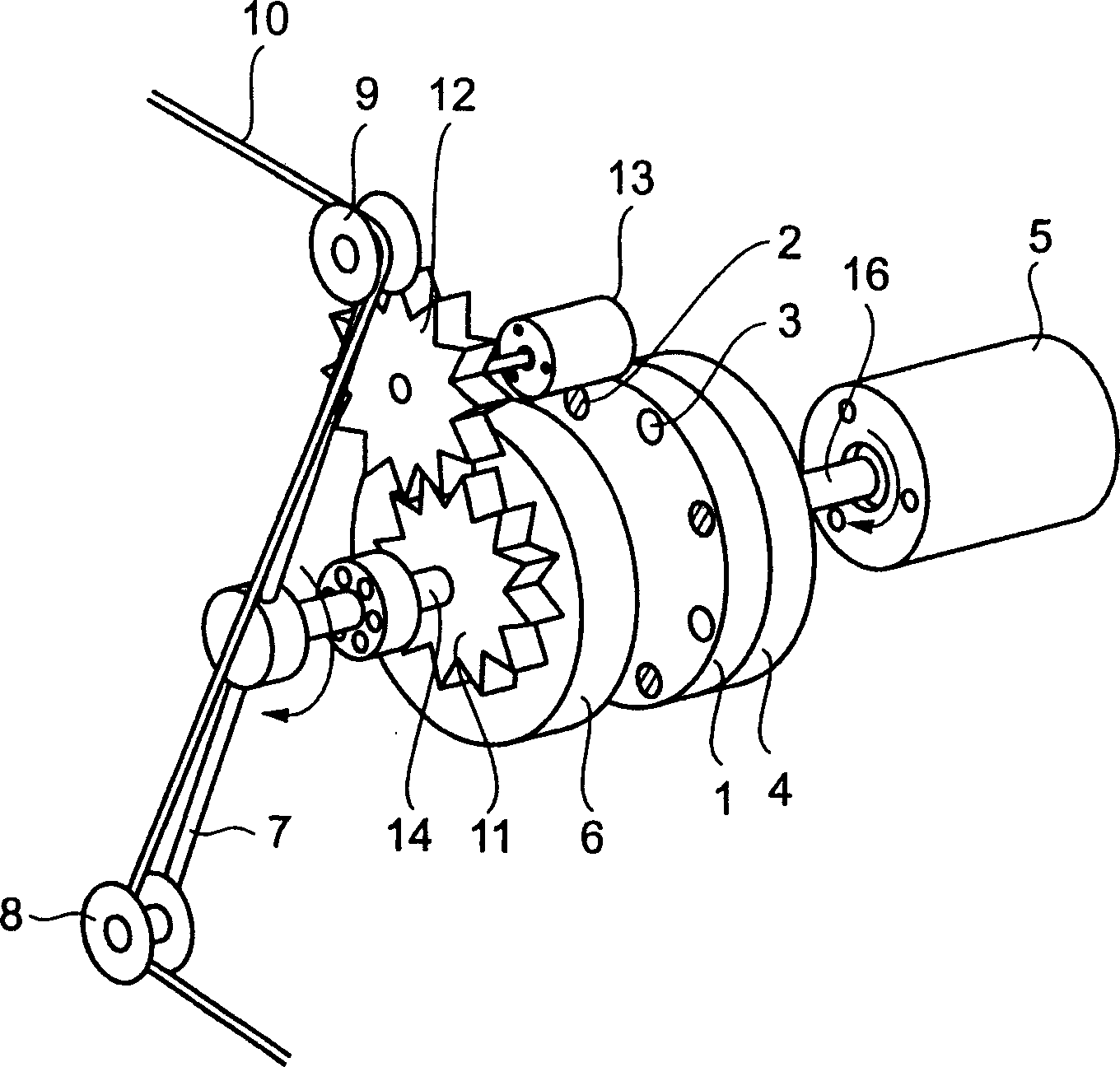
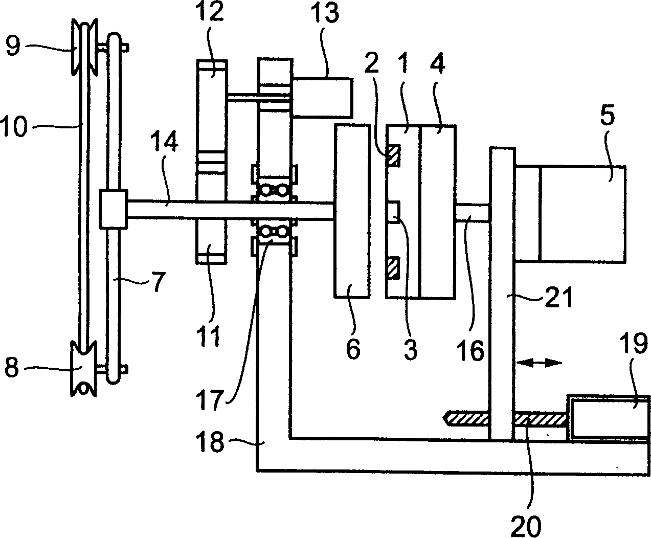
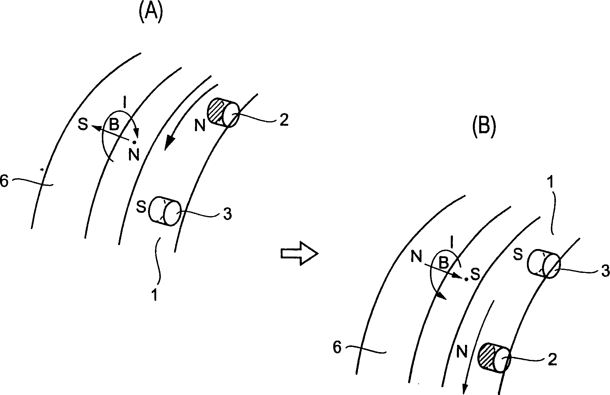
[0027] figure 1 It is a schematic configuration diagram showing a device in an embodiment of the present invention, figure 2 To represent the schematic side view of the device of the embodiment of the present invention, image 3 It is an explanatory diagram of the tension application method in the present invention, Figure 4 It is an explanatory diagram of a schematic configuration and a control method of a wire winding machine equipped with the tension applying device of the present invention.

[0028] 1 in the figure is a disk-shaped non-magnetic plate made of non-magnetic materials such as aluminu...


PUM


Abstract

Disclosed is a device and method for providing tension to wires of a wire take-up machine by a simple and low-cost construction while capable of configuring the tension of the wire take-up machine within a wide range, characterized in including: a non-magnetic plate where NS poles of permanent magnets are provided in a circumferential direction in an alternate manner, being driven to rotate by a rotating means; a conductive plate, spaced from the non-magnetic plate by a specific distance in a rotatable manner, and including an integrally formed support having a wire guide at a front end thereof; and a magnetic field generated by the rotating means which drives rotation of the non-magnetic plate and acted on the conductive plate due to electromagnetic induction, such that a twisting effect is generated between the magnetic field and the permanent magnets for rotating the conductive plate and support thereby providing tension to wires.

Description

technical field [0001] The present invention relates to a wire tension applying device and a tension applying method of a winding machine for transformer winding and winding of various spools, in particular to a tension applying device on a winding machine capable of setting a wide range of tension values ​​with a simple structure and tension application method. Background technique [0002] A tensioning device that applies a constant tension to the wire is used on a winding machine for winding transformer wire and various bobbins. As such a tension applying device, for example, in Japanese Patent Application Laid-Open No. 4-292379 (prior art), there is shown a device that uses a cylinder to apply tension to a wire and a device connected thereto to detect changes in tension. The adjustment roller is composed of, when the position of the elastic adjustment roller moves up and down according to the change of the tension, the speed of the conveying roller can be adjusted, so t...

Claims


Application Information

Patent Timeline
IPC IPC(8): H01F41/06B65H59/00
CPCB65H59/12B65H2511/212B65H2555/41
Inventor 遊佐正行
Owner NITTOKU ENG CO LTD
Why Eureka
Try Eureka