Bottle with bottom hanging device, forming method and injection mould

A bottle and hanger technology, applied in the fields of bottles and their forming methods and injection molds, can solve the problems of limited depth of concave parts, limited size of hanging pieces, increased cost, etc.

Inactive Publication Date: 2004-03-24
A K TECH LAB INC
View PDF0 Cites 0 Cited by
  • Summary
  • Abstract
  • Description
  • Claims
  • Application Information

AI Technical Summary

Problems solved by technology

[0002] As an infusion bottle that can be lifted, the hanging piece is integrally formed at the bottom of the direct blow molding by pinching off, but since the hanging piece protrudes from the outside of the grounding surface, even the hanging piece can be bent freely , the hanging piece will also become an obstacle, so there is a problem that it cannot be transported and filled by standing on its own like ordinary bottles
[0003] In addition, even if it is a bottle manufactured by stretch blow molding an injection-molded preform, the bottom surface is formed with a raised bottom, and a freely bendable hanging piece is formed in the concave portion formed at the bottom, or the injection port is Flattened to form a hanging piece, however, due to the limited depth of the recess, the size of the hanging piece is also limited, and a satisfactory hanging piece cannot be formed. To form the hanging piece, a special bottom shape is required, and drilling, etc., are required. Sub-processing, so it is easy to increase the cost
[0004] As the hanger for the bottom of the bottle, the umbrella-shaped hook is the most simple and reliable. However, due to the deformation of the bottom during forming, the bottom umbrella-shaped hook formed by stretch blow molding must be vertical. The shape is extremely difficult, even if there is a slight inclination, it will be regarded as a defective product, so the yield rate is low, and there is a problem that it is difficult to implement

Method used


Image

  • Bottle with bottom hanging device, forming method and injection mould
  • Bottle with bottom hanging device, forming method and injection mould
  • Bottle with bottom hanging device, forming method and injection mould

Examples


Embodiment Construction

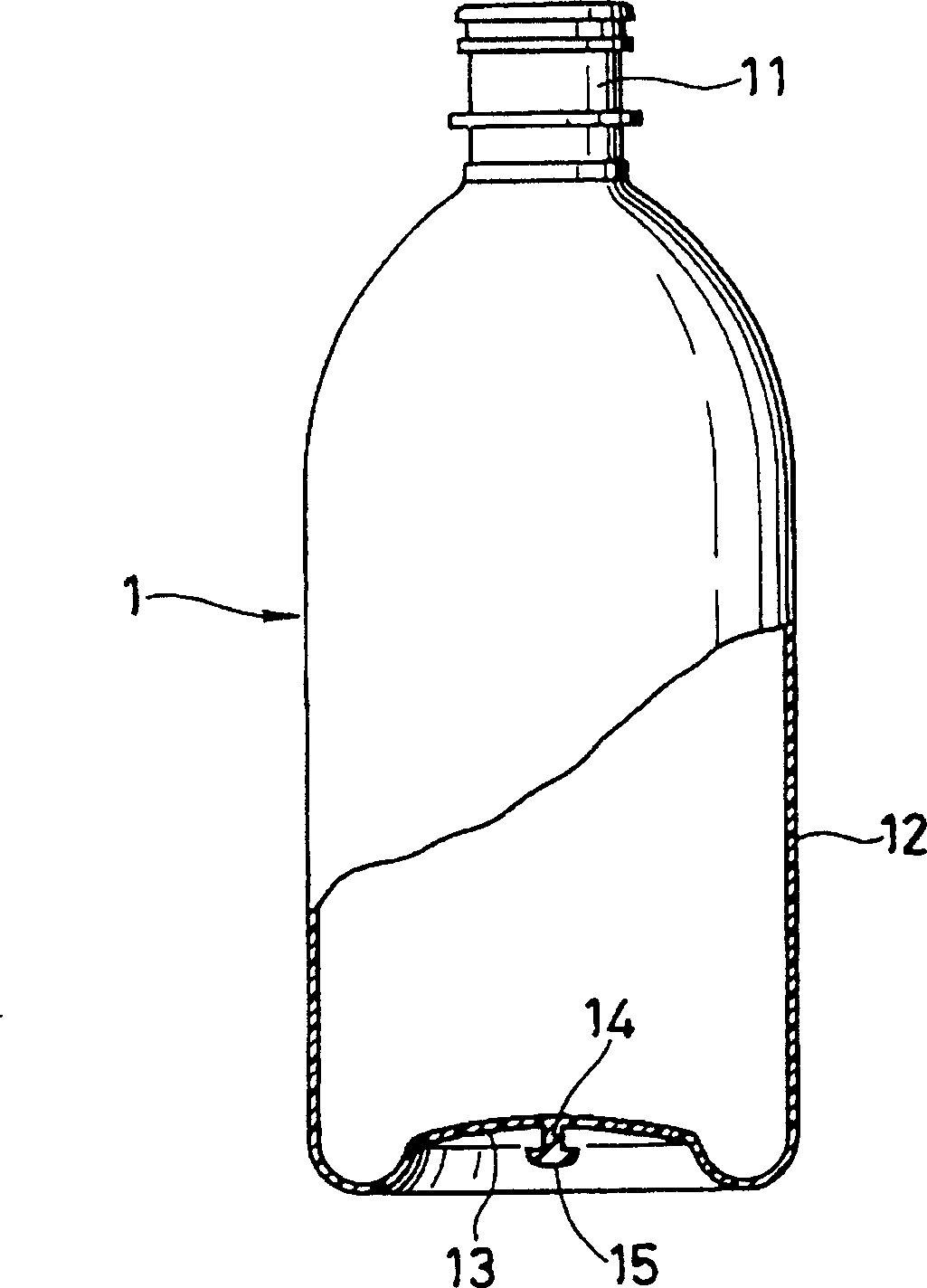
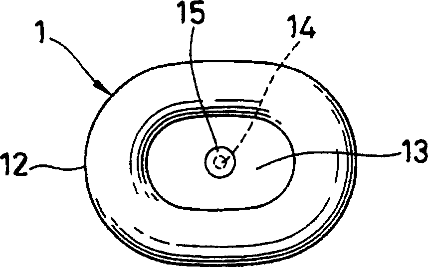
[0016] figure 1 as well as figure 2 It is an infusion bottle 1 made of polypropylene (PP). The bottle body 12 connected to the bottleneck 11 and the bottle bottom 13 concave into the bottle are stretched and blow molded into a thin wall thinner than the bottleneck 11. At the bottom of the bottle The center of 13 integrally forms the suspender of the umbrella-shaped suspension hook that is made up of pillar 14 and flange 15.

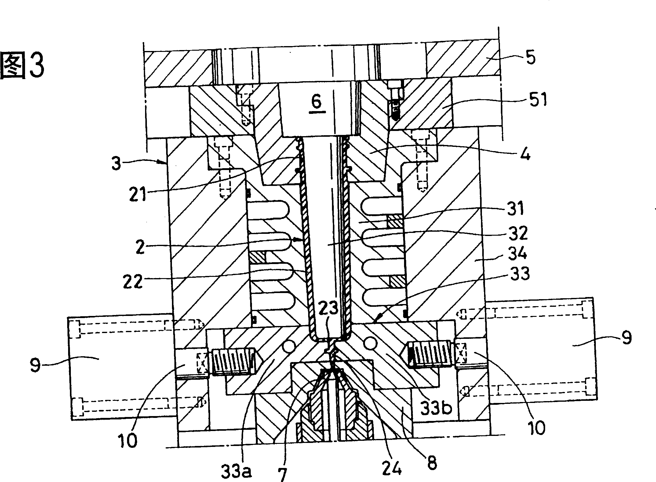
[0017] The bottle 1 with the hanger is formed as follows, that is, the neck 21 and the bottle body 22 and the bottom 23 are integrally injection molded with the injection mold shown in Figure 5 The blow mold 100 shown below stretch-blows the preform 2 into a thin-walled bottle, protruding from the base end portion of the sprue base end 24 provided at the center of the bottom of the preform 2 , and integrally molding around the sprue. The flange 25 becomes the above-mentioned pillar 14 and the flange 15 protruding from the outer bottom surface of the b...


PUM


Abstract

To mold a hanger by a straight umbrella-shape hook on the bottom part of a bottle by drafting-blow molding by improving the bottom structure of a preform and a drafting-blow molding means. This thin bottle 1 is molded by draft-blowing the preform 2 which is injection-molded. At the center of the bottom part 13 which is indented in the bottle, a hanger by the umbrella-shape hook comprising a support 14 and a flange 15 is provided. The hanger is formed of a flange which is integrally formed around a sprue on the bottom surface of the preform and the sprue proximal part.

Description

technical field [0001] The invention relates to a bottle, its forming method and an injection mold. There is an integral hanger at the bottom of the stretch-blow-molded thin-walled bottle, which can be reversely lifted. Background technique [0002] As an infusion bottle that can be lifted, the hanging piece is integrally formed at the bottom of the direct blow molding by pinching off, but since the hanging piece protrudes from the outside of the grounding surface, even the hanging piece can be bent freely , The hanging piece will also become an obstacle, so there is a problem that it cannot be transported and filled by standing on its own like ordinary bottles. [0003] In addition, even if it is a bottle manufactured by stretch blow molding an injection-molded preform, the bottom surface is formed with a raised bottom, and a freely bendable hanging piece is formed in the concave portion formed at the bottom, or the injection port is Flattened to form a hanging piece, howe...

Claims


Application Information

Patent Timeline
Patent Type & Authority Applications(China)
IPC IPC(8): B65D1/02A61J1/05A61J1/16B29B11/08B29C49/06B29L22/00B65D23/00
CPCB29C2049/023B29B11/08B29C45/26B29C49/06B29C49/12B29L2031/7158
Inventor 石川浩
Owner A K TECH LAB INC
Why Eureka
Try Eureka