X-ray fluuorroscopy device

A grid structure and ground grid technology, applied in underwater structures, infrastructure engineering, nets, etc., to achieve the effect of enhancing resistance, enhancing multi-directional performance, and improving flexural modulus

Inactive Publication Date: 2004-03-31
TENSAR TECH
View PDF7 Cites 20 Cited by
  • Summary
  • Abstract
  • Description
  • Claims
  • Application Information

AI Technical Summary

Problems solved by technology

But people have realized that when testing between these two directions, there are deficiencies in the structure

Method used


Image

  • X-ray fluuorroscopy device
  • X-ray fluuorroscopy device
  • X-ray fluuorroscopy device

Examples


Embodiment 1

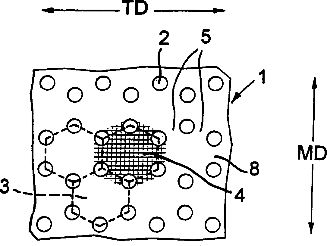
[0073] Figure 7 for figure 1 An enlarged view of a portion of the starting material of , and shows the pitch (distance between centers) of holes 2 . The starting sheet 1 is typically nominally 4.7 mm thick polypropylene with 2% added carbon black, the hole 2 punched to a size of 5 mm diameter. It will be seen that the hexagons 3 do not have sides of equal length, but are slightly shortened in the MD, and within each hexagon 3, the distances between the two opposing holes 2 on the (18.5) MD axis of the hexagon 3 The ratio of the distance between the centers to the distance between the other remaining pairs of opposite holes 2 (21.7 mm) is 0.85:1 (or 1:1.17). The primary MD pitch:secondary MD pitch ratio was 2.625:1, and the ratios between the center distance separating adjacent holes and the diameter of the holes were 2.1:1 and 2.06:1, respectively.

[0074] Starting material 1 was first (imaginary MD) stretched to a draw ratio of 3.86:1 and allowed to relax to a draw rati...

Embodiment 2

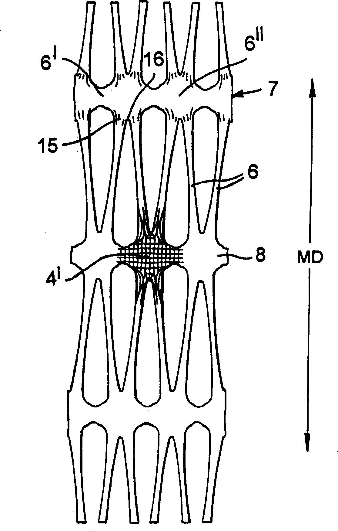
[0077] Figure 8 corresponds to Figure 7 , but if Figure 8 Dimensions shown in may vary. Hexagon 3 has sides of equal length. The punching size for hole 2 is also 5mm in diameter. The ratio between the distance separating the centers of adjacent holes 2 measured along the line connecting the centers and the width of the holes 2 was 2.30:1. Other parameters are:

[0078] Starting flake thickness - 4.7 mm.

[0079] Primary MD Pitch: Secondary MD Pitch - 2.6:1.

[0080] MD distance between centerlines of adjacent bars 6 after first stretching - 60mm

[0081] TD junction center / joint center distance after first stretch (after relaxation)—21.3mm

[0082]TD junction center / joint center distance after second stretch (after relaxation) - 69.3 mm

[0083] Intermediate MD stretch ratio (before relaxation) - 3.82:1

[0084] Intermediate TD stretch ratio (before relaxation) - 3.31:1 (including relaxation allowance)

[0085] Final MD stretch ratio (after relaxation) - 3.76:1 ...

Embodiment 3

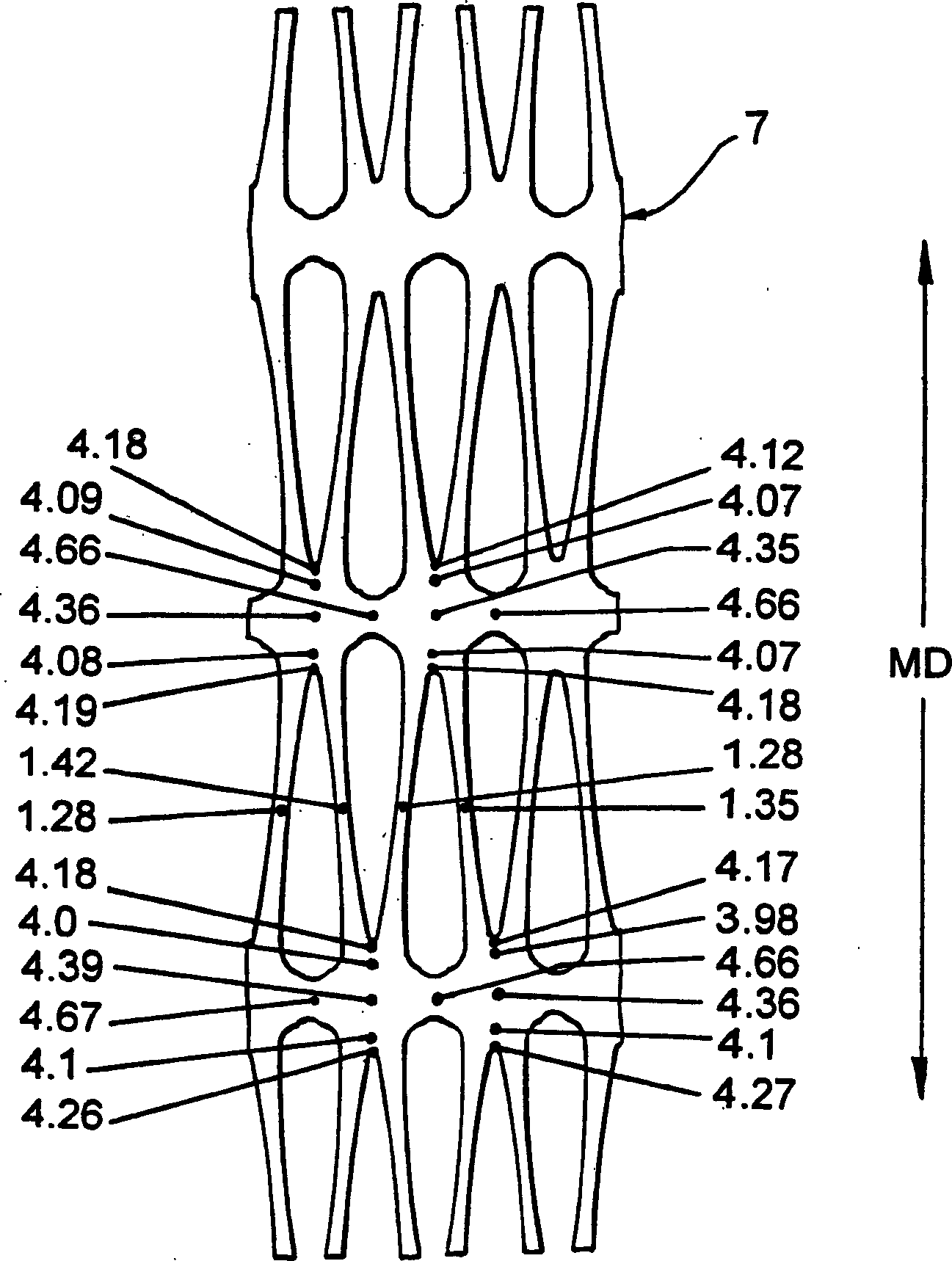
[0100] The thickness, material and punch size of the starting sheet were the same as in Example 1. The imaginary MD pitch is 10.5 mm and the imaginary TD pitch is 9.5 mm. The punches forming the slots 23 had an angle of 116° with radial tips applied to each surface of the material 21 to a depth of 16% of the sheet thickness, forming 32% of the total slotting of the sheet thickness. The MD and TD stretch ratios were 4.00:1 and 2.21:1, respectively. Figure 12 The thickness at different points on the product is shown in millimeters. The geometric measurement extension is 2.3%. The relative lateral displacement was 11.8%.


PUM

PropertyMeasurementUnit
thicknessaaaaaaaaaa
thicknessaaaaaaaaaa
thicknessaaaaaaaaaa

Abstract

To make an oriented plastics material geogrid in which oriented strands form triangular meshes with a junction at each corner and six of the strands meet at each junction, a plastics material sheet starting material has holes in an array of hexagons, opposite holes of each hexagon being aligned in the machine direction, and the starting material is stretched first in the machine direction and secondly in the transverse direction. In the eventual geogrid, the centre portions of the hexagons in the starting material form the junctions. The centres of the junctions are slightly biaxially oriented, but at the edges of the junctions, the orientation of the edge of substantially each strand runs around the edge of the respective junction and into the edge of the next strand. During the second stretch, restraint can be applied in the first stretch direction and discontinued before the material is allowed to relax in the second stretch direction.

Description

technical field [0001] The present invention generally relates to a ground grid, but is generally suitable for application to grid structures. A ground grid is a grid whose primary purpose is to strengthen or consolidate soil and which has a grid of openings in which soil particles can be locked. If the grid is made by orienting a plastic starting material, the starting material typically has a thickness greater than about 1.5 millimeters or 2 millimeters. The ground grid is actually connected to each other by bars arranged across the ground grid in the TD direction, or twisted wires (also known as ribs) connected to each other at the intersection (also known as node or intersection point). constitute, whether or not these strands are continuous through the ground grid as in the braided ground grid described. The thickness of the grid, measured at the intersection, will be greater than about 0.5 mm or 0.75 mm, and may be greater than about 1.00 mm or 1.5 mm or 2 mm. If poss...

Claims


Application Information

Patent Timeline
Patent Type & Authority Applications(China)
IPC IPC(8): E02D17/18B29C55/00B29C55/14B29D28/00E02D17/20E02D29/02
CPCE02D29/0241B29D28/00B29C55/14Y10T428/24273B29C55/02B29C55/10
Inventor 安东尼·托马斯·华莱士
Owner TENSAR TECH
Why Eureka
Try Eureka