
Castor type roller controlled by motor

A technology of small casters and rollers, applied in casters, electric steering mechanisms, wheels, etc., can solve problems such as complex structures

Inactive Publication Date: 2004-03-31
TENTE
View PDF1 Cites 11 Cited by
  • Summary
  • Abstract
  • Description
  • Claims
  • Application Information

AI Technical Summary

Problems solved by technology

This structure is also quite complex

Method used


Image

  • Castor type roller controlled by motor
  • Castor type roller controlled by motor
  • Castor type roller controlled by motor

Examples


Embodiment Construction

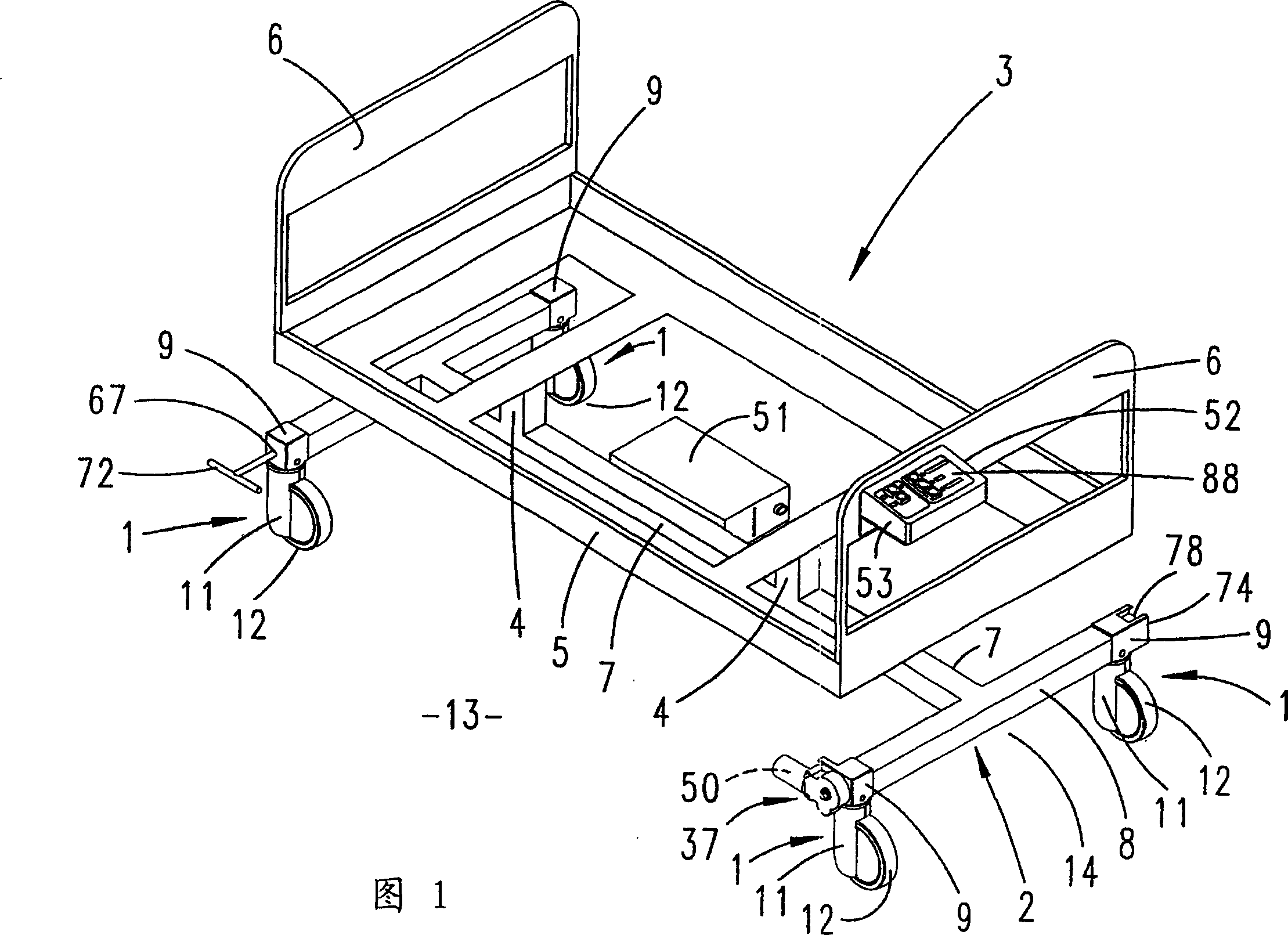
[0024] The rollers 1 according to the invention are made in the form of castors and mounted on the four corners of the mobile mechanism. In the case of the described embodiment, this movement mechanism is the underframe 2 of the hospital bed 3 .

[0025] The underframe 2 is connected to the bed frame 5 by the uprights 4 . The head and feet of the bed frame are vertical boards 6 .

[0026] The bed frame 5 can be separated so that the parts of the frame can be adjusted and fixed to each other to form a bed of a specific profile (not shown in these profile drawings).

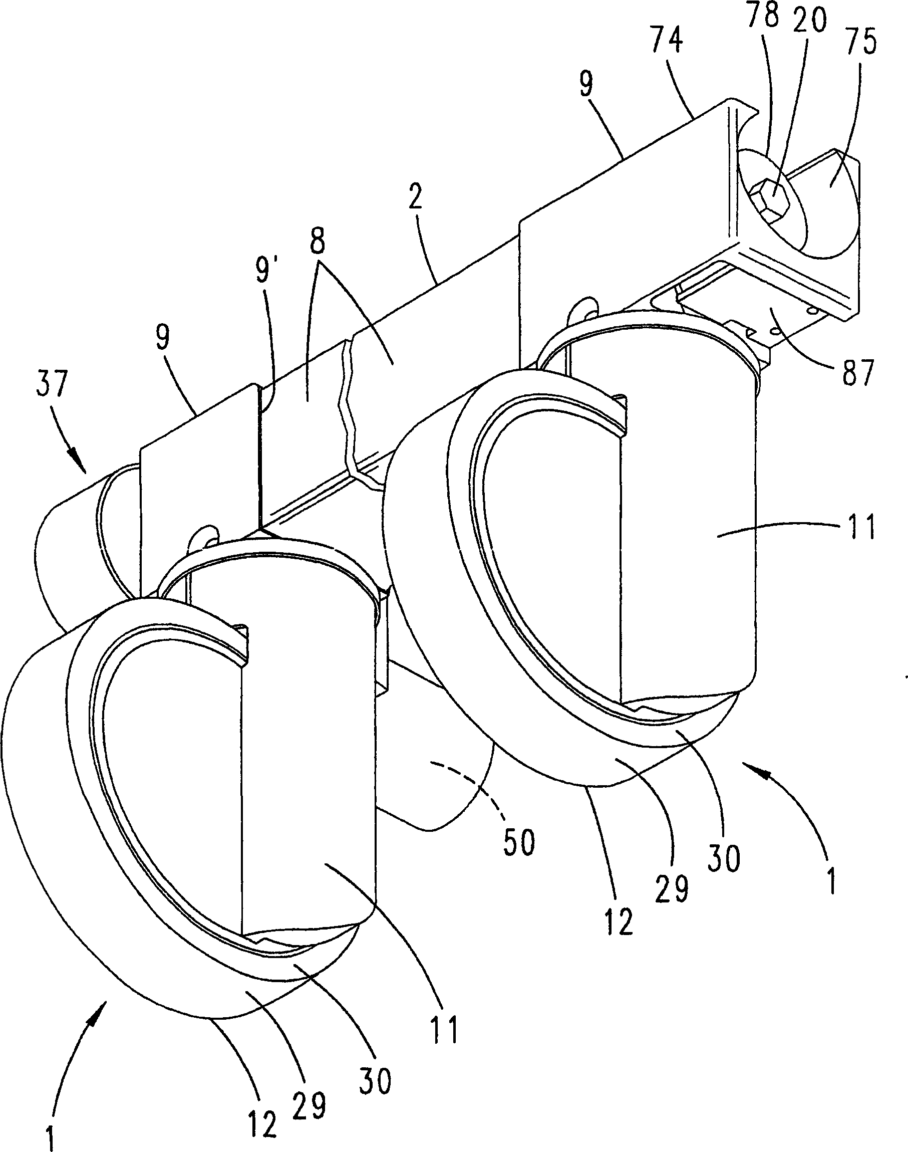
[0027] The chassis 2 is assembled from box parts. The box part comprises a beam 7 as a T-bar; and an arm 8 intersecting the beam 7 at the front end of the bed head. The beam 7 and the arm 8 form two T-shaped intersections.

[0028] The roller 1 is mounted on the free end of the arm 8 by means of a support 9 which can be inserted horizontally. The plug-in connection can be made upside down and secured with a cr...


PUM


Abstract

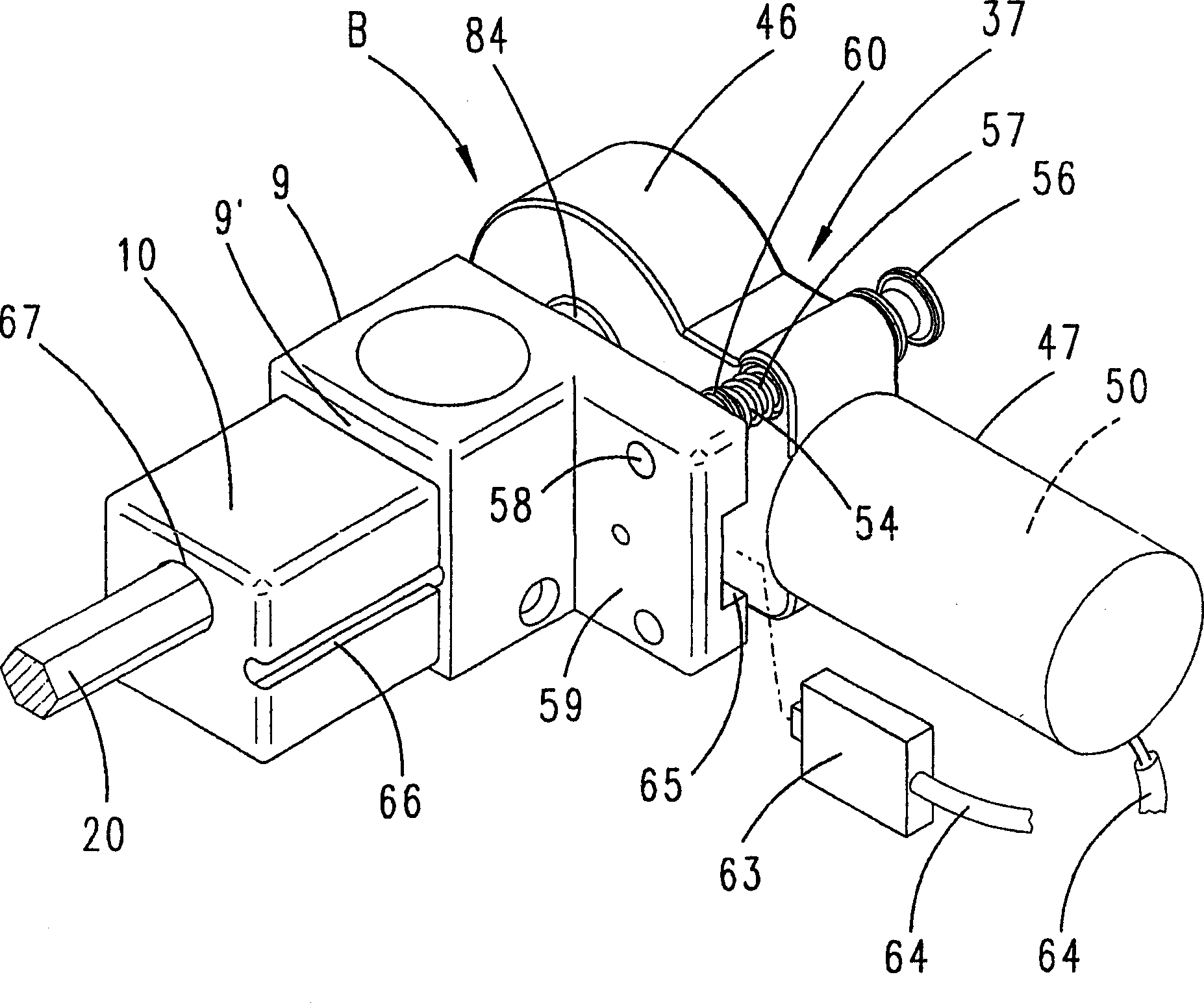
The invention relates to a roller (1),in particular, a castor. The rotation of the running wheel of said castor and optionally the pivoting motion of the running wheel (12) may be fixed, by means of an operating shaft (20), which moves a control cam (19) through the roller (1), with an electric motor (37) acting thereupon for operation thereof. According to the invention, the functional roller operation can be embodied with a more advantage operation, a simpler construction, yet of secure operation, whereby the electric motor (37) acts on the operating shaft (20) by means of an electric motor shaft (39) using a toothed gear (38).

Description

technical field [0001] The present invention relates to a roller; in particular, it relates to a caster-type roller in which the turning motion of the turning wheel and the turning movement of the turning wheel around the fulcrum are fixed. The working shaft passes through the control cam of the roller, and the motor acts on the roller through the gear mechanism to make the roller work. Background technique [0002] U.S. Patent No. 5,377,372 discloses a roller that can fix the rotary motion of the running wheel and the rotary motion around the support, and utilize the rocker pedal to switch. This pedal protrudes into the center of the chassis of the movable bed, which makes the gearing of the rollers rather complicated. [0003] From DE-A1 4318546 it is known to use an electric motor to control the working shaft of the control cam via the rollers. The motor and the gear mechanism drive a push rod, and the push rod rotates the working shaft through a hinged lever that rotat...

Claims


Application Information

Patent Timeline
Patent Type & Authority Applications(China)
IPC IPC(8): B60B33/00A61G7/05A61G7/08B60B33/02B60T1/04F16H1/06F16H1/16F16H25/18
CPCB60B33/026B60B33/0068B60B33/0057A61G2007/0528B60B33/0092B60B33/0049B60B33/0081A61G7/08B60B33/025B60B33/0073B60B33/0039B60B33/021A61G7/0528
Inventor 沃尔夫冈·布洛克曼弗雷德·米尔布雷特
Owner TENTE
Learn More