Magnetic resonance imaging equipment

A technology of magnetic resonance imaging and equipment, applied in magnetic resonance measurement, measurement using nuclear magnetic resonance imaging system, material analysis through resonance, etc., can solve problems such as inconsistency of sensitivity matrix

Inactive Publication Date: 2004-04-07
GE MEDICAL SYST GLOBAL TECH CO LLC
View PDF0 Cites 11 Cited by
  • Summary
  • Abstract
  • Description
  • Claims
  • Application Information

AI Technical Summary

Problems solved by technology

This is because when using the pilot echo to correct the phase of the imaging echo, the phase originating from the sensitivity of the receiving system does not have to be corrected, resulting in an inconsistency with the sensitivity matrix

Method used


Image

  • Magnetic resonance imaging equipment
  • Magnetic resonance imaging equipment
  • Magnetic resonance imaging equipment

Examples


Embodiment approach

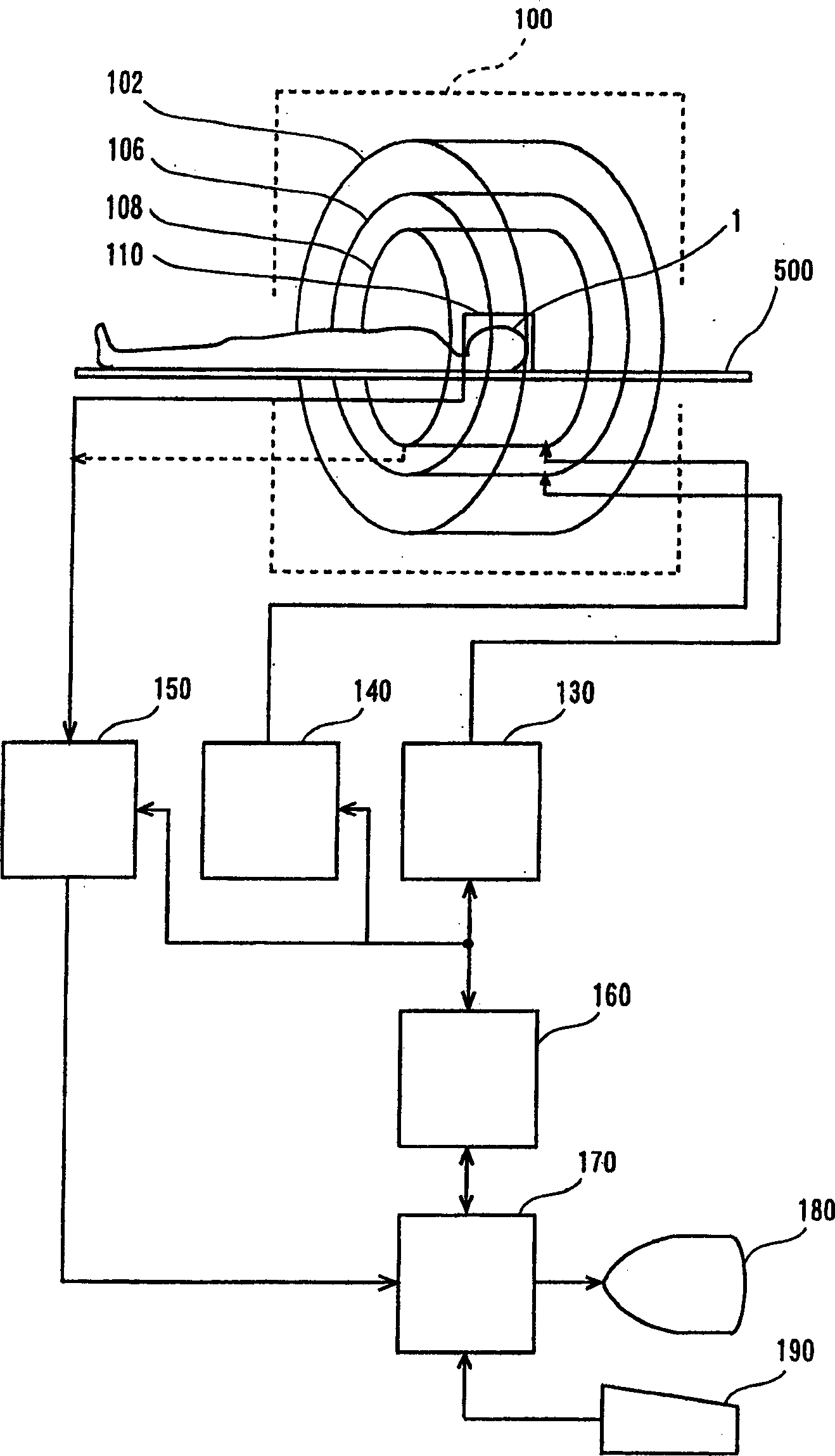
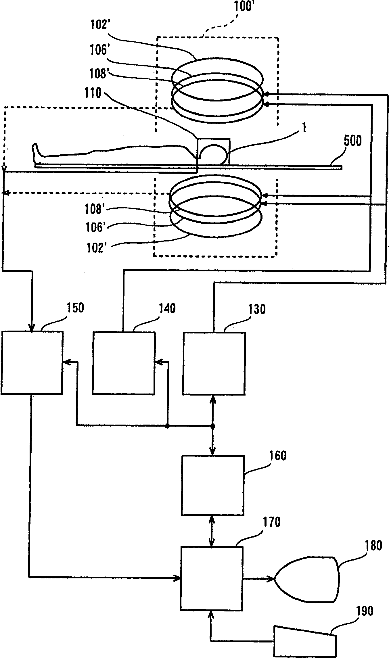
[0144] The phase correction unit 804 performs phase correction on imaging echoes. The phase corrector 804 and this device are in Figure 8 The function described in step 709 is corresponding. The phase correction unit 804 is an embodiment of the first correction device of the present invention.

[0145] The intermediate image generation unit 806 generates an intermediate image based on the phase-corrected imaging echoes. The intermediate image generation unit 806 and the Figure 8 The function of the device described in step 711 is corresponding. The intermediate image generation unit 806 is an embodiment of the first image generation device of the present invention.

[0146] The sensitivity matrix generator 808 generates a sensitivity matrix. Sensitivity matrix generator 808 and in Figure 8 The functions of the device described in steps 701 and 703 are corresponding. The sensitivity matrix generator 808 is an embodiment of the generator of the present invention.

[0...


PUM


Abstract

For the purpose of enabling parallel imaging even when a navigator echo is used to phase-correct an imaging echo, the present invention involves: exciting spins within a subject to acquire an imaging echo generated by the excited spins along with a navigator echo, with a reduced field-of-view via a plurality of receiver systems (802); conducting phase correction on the imaging echo based on the navigator echo (804); producing an intermediate image based on the phase-corrected imaging echo from each of the plurality of receiver systems (806); generating a sensitivity matrix for the plurality of receiver systems (808); correcting the phase of matrix data in the sensitivity matrix (810); and producing an image with a full field-of-view based on the intermediate image and the phase-corrected sensitivity matrix (812).

Description

technical field [0001] The present invention relates to magnetic resonance imaging apparatus, in particular to magnetic resonance imaging apparatus performing parallel imaging. Background technique [0002] In a magnetic resonance imaging (MRI) device, the object to be imaged is sent into the inner space of an electromagnetic system, that is, the imaging space. In this space, a static magnetic field is formed, and the applied gradient magnetic field (gradient magnetic field) And a radio frequency (RF) magnetic field is used to excite spins (spin) in the subject to generate a magnetic resonance signal, and an image is reconstructed from the received signal. [0003] One option for such magnetic resonance imaging is parallel imaging. Parallel imaging can be found, for example, in the paper "SENSE: Sensitivity Encoding for Fast MRI" by Klaas P. Pruessmann et al. [0004] In general terms, in parallel imaging, magnetic resonance signals are acquired by multiple receiving syste...

Claims


Application Information

Patent Timeline
Patent Type & Authority Applications(China)
IPC IPC(8): G01R33/54A61B5/055G01R33/48G01R33/561
CPCG01R33/5611G01R33/56554A61B5/055
Inventor 池崎吉和
Owner GE MEDICAL SYST GLOBAL TECH CO LLC
Why Eureka
Try Eureka