Liquid crystal display device

A liquid crystal display device, liquid crystal technology, applied in optics, instruments, nonlinear optics, etc.

Inactive Publication Date: 2004-04-07
SHARP KK
View PDF2 Cites 29 Cited by
  • Summary
  • Abstract
  • Description
  • Claims
  • Application Information

AI Technical Summary

Problems solved by technology

[0006] However, at present, in the case of wishing to obtain a liquid crystal display device with a wider viewing angle and higher display quality, the contrast ratio when viewed obliquely is required to be improved, but using the above-mentioned registered patent No. 2947350 and the The situation of the retarded films 116 (114, 115) described in Kai 2000-39610 is certainly not sufficient, and there is still room for improvement.

Method used


Image

  • Liquid crystal display device
  • Liquid crystal display device
  • Liquid crystal display device

Examples


Embodiment 1

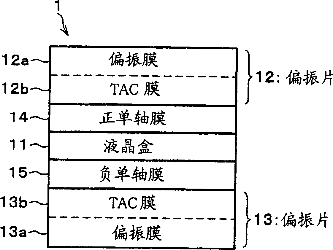
[0097] In this embodiment, as the liquid crystal cell 11, liquid crystal cells having a refractive index anisotropy Δn of the liquid crystal layer 11c of 0.08 and a thickness (cell thickness dlc) of 3.0 [micrometer], 4.0 [micrometer], and 5.0 [micrometer] were prepared. , that is, the retardation Rlc (=dlc·Δn) in the thickness direction is respectively 24 0 [nm], 320 [nm] and 400 [nm] of the liquid crystal cell. In addition, TAC films having retardation Rtac in the thickness direction of 0 [nm], 30 [nm], 50 [nm], and 80 [nm] were prepared as the TAC films 12 b and 13 b. In addition, Rp and Rn at which the contrast ratio when viewed from an oblique direction is maximized were obtained for each of the combinations of the liquid crystal cells 11 and the TAC films 12b and 13b. As a result, get Figure 7 The experimental results shown.

[0098] Furthermore, when measuring the contrast, the viewing angle when the liquid crystal display device 1 is actually used, that is, the inclu...

Embodiment 2

[0122] In this example, the same liquid crystal cell 11 and TAC films 12b, 13b as in Example 1 above were prepared, and for each combination of the two, when viewed from the same oblique direction as in Example 1, the Contrast becomes the largest Rp and Rn. From this, got Figure 11 The experimental results shown.

[0123] Thus, if Figure 9 As shown, when the stacking order of the positive uniaxial film 14 is arranged between the negative uniaxial film 15 and the liquid crystal cell 11, and the retardation Rp in the in-plane direction of the positive uniaxial film 14 is the same as the above-mentioned parameter α2, the negative When the retardation Rn in the thickness direction of the uniaxial film 15 is the same as the above-mentioned parameter β2, the liquid crystal display device 1b in which the maximum contrast can be obtained can be confirmed. In addition, from the above experimental results, the above formulas (5) and (6) can be calculated.

[0124] In addition, in ...

Embodiment 3

[0156] In this example, the same liquid crystal cell 11 and TAC films 12b, 13b as in Example 1 above were prepared, and for each combination of the two, when viewed from the same oblique direction as in Example 1, the Contrast becomes the largest Rxy and Rxy. From this, got Figure 15 The experimental results shown.

[0157] Such as Figure 12 As shown, when the lamination sequence of the biaxial film 16 is arranged between the liquid crystal cell 11 and one of the polarizers 12 and 13 (in the case of the illustration, the polarizer 12), and in the plane of the biaxial film 16 When the directional retardation Rxy is the same as the parameter α3 described above, and the retardation Rz in the thickness direction of the biaxial film 16 is the same as the parameter β3 described above, the liquid crystal display device 1c that can obtain the maximum contrast can be confirmed. Also, by approximating the above experimental results with a linear equation, the above equations (9) an...


PUM


Abstract

A positive uniaxial film (14) with a retardation of Rp [nm] in an in-plane direction is provided between a vertical alignment mode liquid crystal cell (11) and a polarizing plate (12), and a negative uniaxial film (15) with a retardation of Rn [nm] in a thickness direction is provided between the liquid crystal cell (11) and a polarizing plate (13). Further, when a parameter alpha1 [nm] relative to Rp is: alpha1=135-0.7xRtac; and a parameter beta1 [nm] relative to Rn is: beta1=Rlc-65-1.4xRtac, where Rtac [nm] is a retardation in a thickness direction of the respective triacetyl cellulose films (12b and 13b) of polarizing plates (12 and 13), the retardations Rp and Rn are set to be values greater than 90% but smaller than 110% with reference to the parameters alpha1 and beta1, respectively. This makes it possible to surely provide a vertical alignment mode liquid crystal display device which can maintain a high contrast when viewed from an oblique direction.

Description

technical field [0001] The present invention relates to a liquid crystal display device in a vertical alignment mode. Background technique [0002] Conventionally, liquid crystal display devices have been widely used as screens of word processors and computers, and in recent years, they have also been rapidly popularized as screens of televisions. Many of these liquid crystal display devices employ a TN (twisted nematic) mode, but these liquid crystal display devices have problems that the contrast tends to decrease and the gradation characteristics tend to be reversed when viewed from an oblique direction. [0003] Therefore, in recent years, liquid crystal display devices of VA (Vertical Alignment) mode have been attracting attention in order to improve the viewing angle characteristics viewed from an oblique direction. The liquid crystal cell of the liquid crystal display device of this mode is constituted by combining a nematic liquid crystal having negative dielectric ...

Claims


Application Information

Patent Timeline
Patent Type & Authority Applications(China)
IPC IPC(8): G02B5/30G02F1/13363G02F1/1337G02F1/139
CPCG02F1/133634G02F1/1393G02F1/1335
Inventor 宫地弘一
Owner SHARP KK
Why Eureka
Try Eureka