Operation method of two-stroke engine fitted with mixed-gas sunction device

An engine and two-stroke technology, which is applied to combustion engines, machines/engines, mechanical equipment, etc., can solve the problem of increasing the amount of lubricating oil added, and achieve good heat transfer and improved heat conduction effects

Inactive Publication Date: 2004-04-14
ANDREAS STIHL AG & CO KG
View PDF2 Cites 3 Cited by
  • Summary
  • Abstract
  • Description
  • Claims
  • Application Information

AI Technical Summary

Problems solved by technology

However, this type of operation of the two-stroke engine requires a separate lubrication system in the crankcase, which is very complicated and may lead to an increase in the amount of lubricating oil in the combustion chamber

Method used


Image

  • Operation method of two-stroke engine fitted with mixed-gas sunction device
  • Operation method of two-stroke engine fitted with mixed-gas sunction device
  • Operation method of two-stroke engine fitted with mixed-gas sunction device

Examples


Embodiment Construction

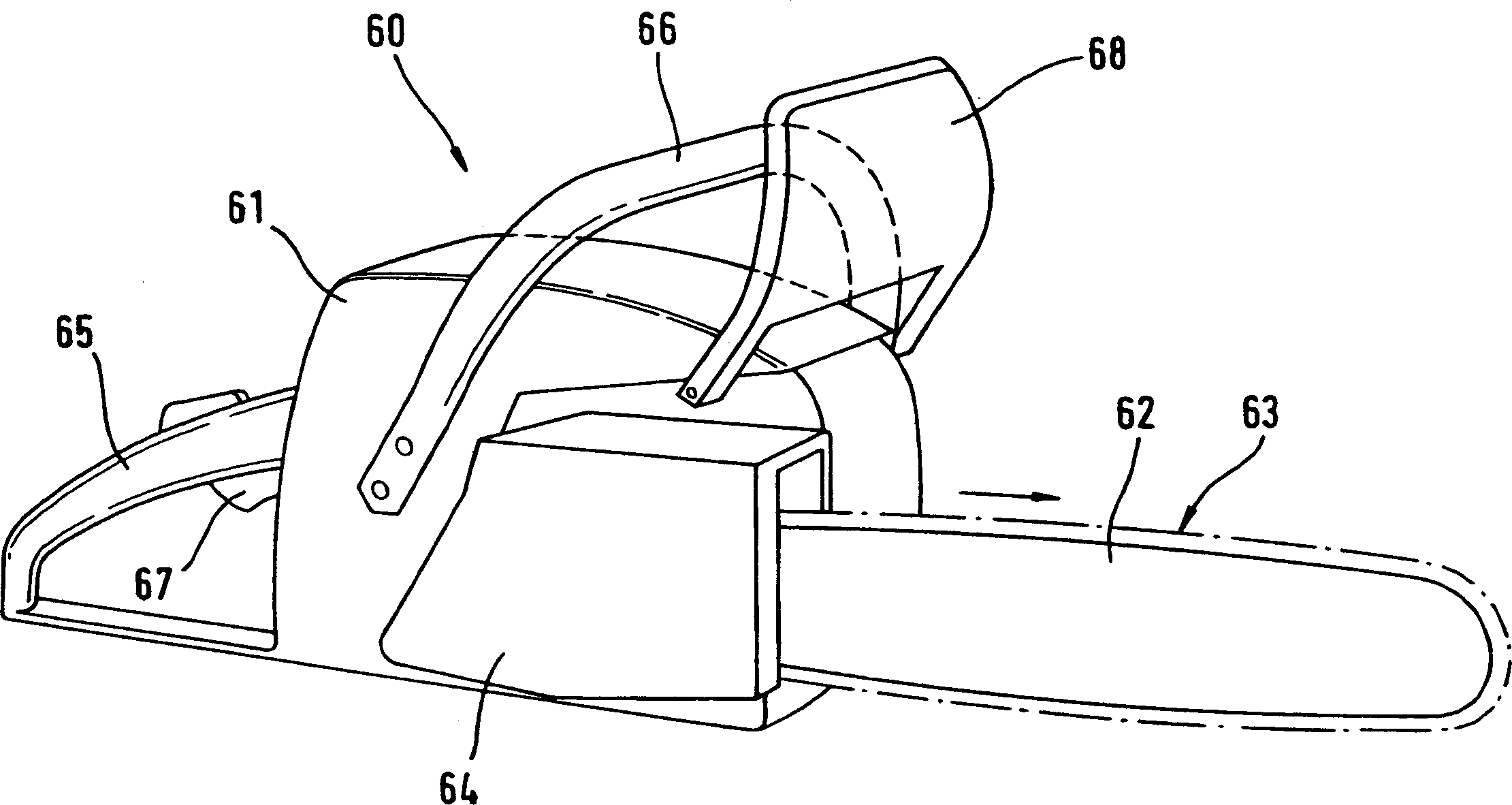
[0021] figure 1 The portable hand-held implement shown in is an electric chainsaw 60 with an internal combustion engine housed in its housing 61, in figure 2 and 6 The internal combustion engine is schematically depicted in . The internal combustion engine drives a tool, in the case of the electric chain saw shown, which is a saw chain 63 that loops on a guide rail 62 . The guide rail is clipped to the housing 61 of the internal combustion engine by means of a sprocket housing 64 . In order to carry and manipulate this implement, a rear handle 65 and an upper handle 66 are provided. A joystick 67 for operating the internal combustion engine is assigned to the rear handle 65 ; a hand guard 68 is arranged in front of the upper, front handle 66 .

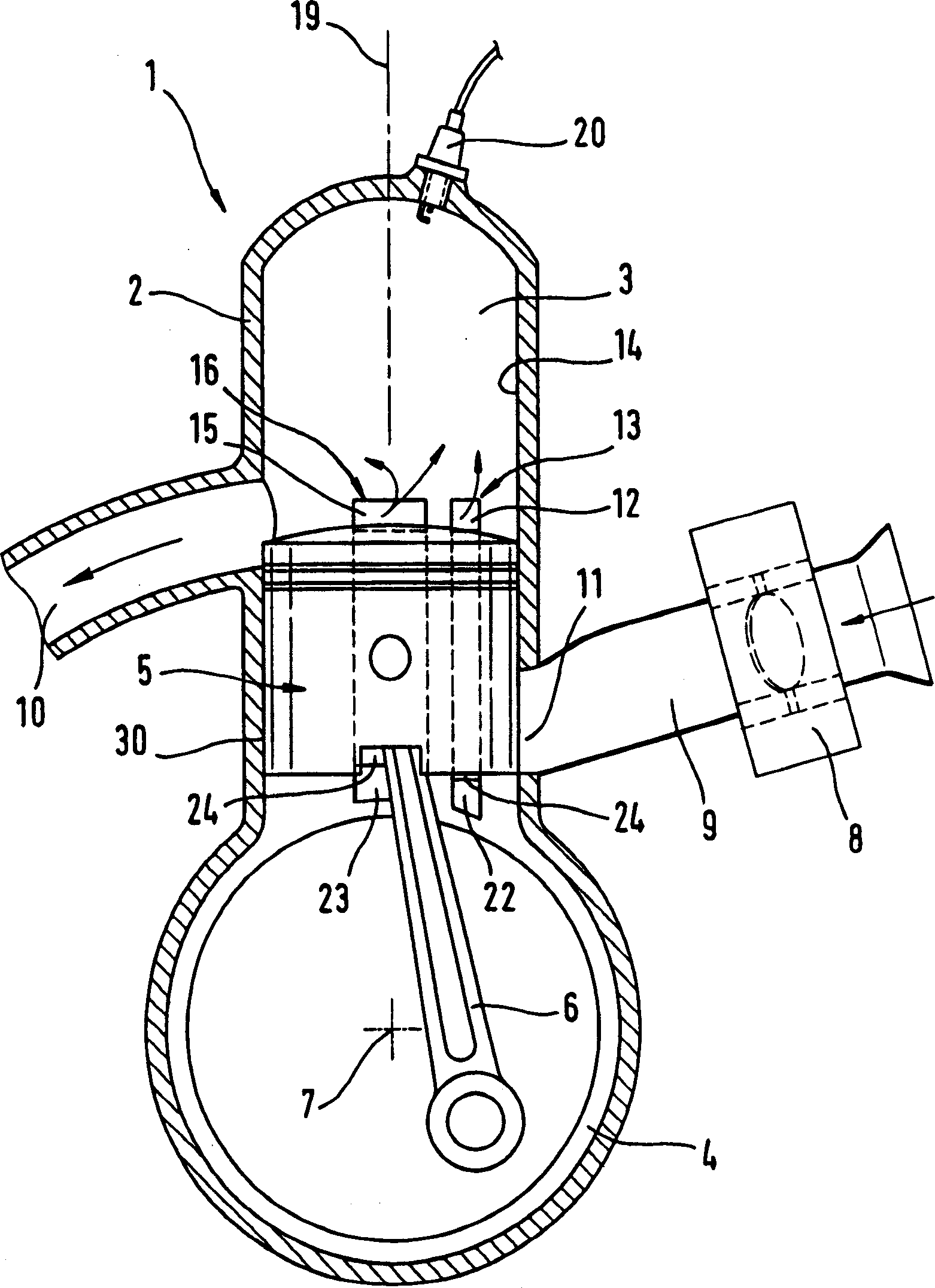
[0022] figure 2 The internal combustion engine 1 schematically depicted in is a two-stroke engine with a scavenging device. It basically consists of a cylinder 2 and a crankcase 4 arranged on the foot of the cylinder 2 . A com...


PUM


Abstract

The invention relates to a method for operating a two-stroke engine having scavenging-advance storage. The combustion chamber (3) which is configured in the cylinder (2) is supplied with an air / fuel mixture via a transfer channel (12, 15). This air / fuel mixture was drawn by induction through an inlet into the crankcase (4) during the intake phase. During the intake phase, a fuel-free fluid such as pure air is inducted via a fluid channel (17) and stored in the transfer channel. To obtain good exhaust-gas values while also having reduced fuel consumption and reliable lubrication, lambda (lambda) of the air / fuel mixture, which is stored in the crankcase (4), is adjusted in a range of approximately 0.2 to 0.6 in the part-load and full-load ranges of the two-stroke engine (1).

Description

technical field [0001] The invention relates to a working method of a two-stroke engine, in particular to a working method of a two-stroke engine used in hand-held tools such as electric chain saws, grinders, free cutters, sandblasting machines, etc., wherein the two-stroke engine has a A combustion chamber arranged in a cylinder, the fuel chamber being limited by a reciprocating piston which drives a crankshaft rotatably arranged in a crankcase through a connecting rod; from the crankcase to the combustion chamber through an overflow pipe The chamber supplies a fuel / air mixture that is drawn into the crankcase through an inlet during the intake phase of the engine; it also has a fluid passage through which the fuel-lean to free air is drawn during the intake phase of the engine Fuel fluid is drawn into the overflow tube and stored therein. Background technique [0002] Disclosed in DE 19900 445 A1 is a two-stroke engine controlled by diaphragm gas distribution. This engine...

Claims


Application Information

Patent Timeline
Patent Type & Authority Applications(China)
IPC IPC(8): F02B17/00F02B25/14F02B25/16F02B25/22F02B63/02
CPCF02B25/22F02B17/00F02B25/14F02B63/02
Inventor C·弗莱格W·盖尔J·施罗萨茨克
Owner ANDREAS STIHL AG & CO KG
Why Eureka
Try Eureka