

Drum-type washing drier
A washer-dryer, drum-type technology, applied in other washing machines, household dryers, washing machines with containers, etc.
- Summary
- Abstract
- Description
- Claims
- Application Information
AI Technical Summary
Problems solved by technology
Method used
Image

Examples
Embodiment 1
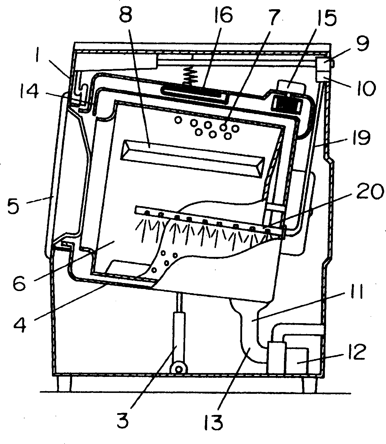
[0039] Such as figure 1 As shown, rotating drum 6 has a rotating shaft substantially inclined, and is rotatably arranged in tub 4 . The water inlet hose 19 communicates with the dry clothes water inlet valve (water inlet device) 10 and the bucket 4. The front end of the water inlet hose 19 is equipped with a nozzle 20, and the nozzle 20 is connected to the water bucket 4 and the rotating drum 6. An opening is provided in the formed space, and cooling water is sprayed between the tub 4 and the rotary drum 6, and the moisture evaporated from the laundry in the tub 4 is dehumidified by the cooling water.
[0040]The operation in the above apparatus will be described below. In the drying process, the rotating drum 6 is driven as in the washing process, and while stirring the laundry in the rotating drum 6, the hot air heated by the blower (blowing device) 15 and the heater (heating device) 16 is passed through. The air outlet 14 is blown onto the clothing in the rotary drum 6, ...
Embodiment 2
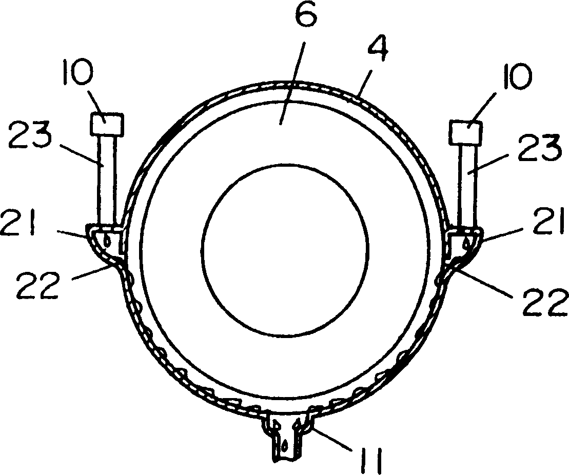
[0045] Such as figure 2 As shown, the cooling nozzle 21 is installed on the wall of the tub 4, and is provided with a plurality of water holes 22 opening into the tub 4, and the cooling nozzle 21 communicates with the dry clothes inlet valve 10 through a water inlet hose 23. , the cooling water flows in from the water hole 22 of the cooling nozzle 21 along the inner wall of the tub 4 for dehumidification. Other constitutions are the same as in the above-mentioned Embodiment 1.
[0046] The operation in the above constitution will be described below. During the clothes drying process, water is supplied from the water inlet hose 23 to the cooling nozzle 21 through the clothes water inlet valve 10 , and the cooling water sent from the plurality of water holes 22 flows in to cool the inner wall of the tub 4 . In this way, the high-temperature air containing steam in the tub 4 is cooled and dehumidified by exchanging heat while being in contact with the inner wall surface of the...
Embodiment 3
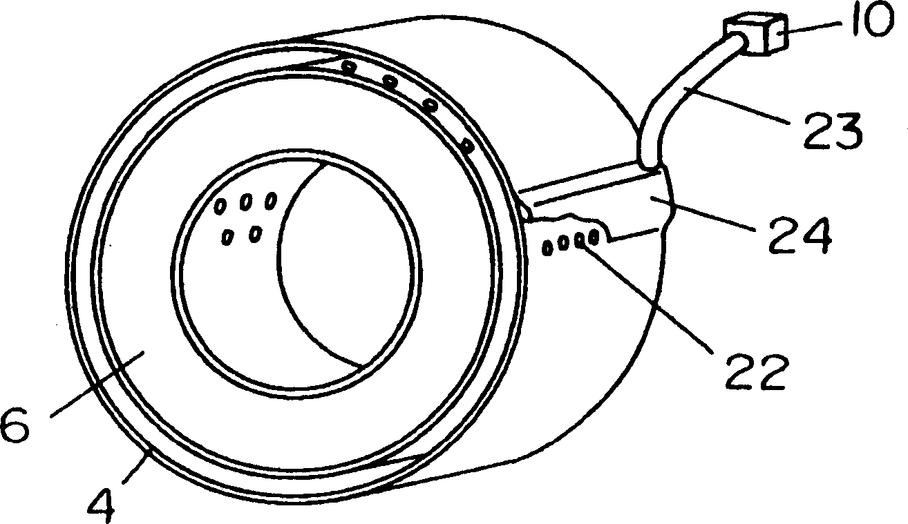
[0049] Such as image 3 As shown, the cooling nozzle (cooling water channel) 24 is used to feed cooling water, it is located on the wall, forms an integral body with the water tub 4, communicates with the dry clothes inlet valve 10 through the water inlet hose 23, and is provided with A plurality of water holes 22 opening into the tub 4 . Other constitutions are the same as those of the above-mentioned embodiment 1 or 2.
[0050] The operation in the above constitution will be described below. During the clothes drying process, water is supplied from the water inlet hose 23 to the cooling nozzle 24 through the clothes water inlet valve 10 , and the cooling water sent from the plurality of water holes 22 flows in to cool the inner wall of the tub 4 . In this way, the high-temperature air containing steam in tub 4 is cooled and dehumidified by exchanging heat while contacting the inner wall surface of tub 4 . The dehumidified air is reheated by the heater 16 and sent into the...
PUM
 Abstract
Description
Claims
Application Information