Miniature turbine jet engines

A technology of jet engine and microturbine, which is applied in the direction of machines/engines, jet propulsion devices, etc., can solve the problem of no microturbine engine, etc., and achieve the effect of increasing the thrust-to-weight ratio and increasing the degree of automation

Inactive Publication Date: 2004-04-21
BEIHANG UNIV
View PDF0 Cites 13 Cited by
  • Summary
  • Abstract
  • Description
  • Claims
  • Application Information

AI Technical Summary

Problems solved by technology

Therefore, up to now, there has not been a microtu

Method used


Image

  • Miniature turbine jet engines
  • Miniature turbine jet engines
  • Miniature turbine jet engines

Examples


Example Embodiment

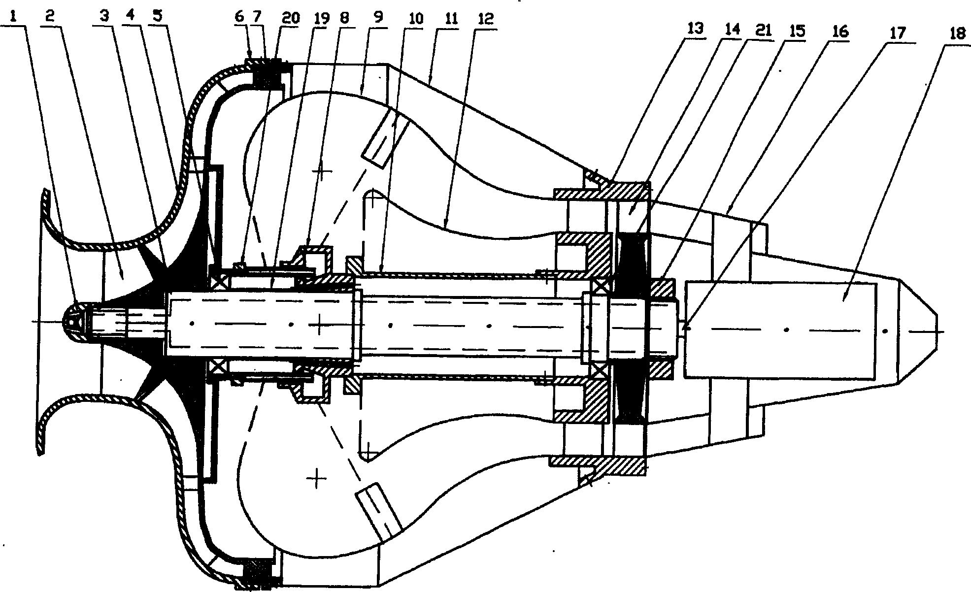
[0023] The present invention will be further described below with reference to the accompanying drawings.

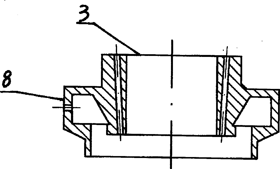
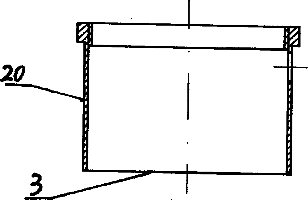
[0024] Please refer to the accompanying drawings, in the figure, the front nut 1 is installed on the front end of the shaft 3, and is used for pressing the centrifugal compressor rotor 2 on the shaft 3, the front bearing 5, the sleeve 19, and the oil slinger 8. A simple centrifugal pump is used to pump air on the front nut 1 to cool the DC motor 18 (as shown in the appendix). Image 6 shown), two symmetrical slanted orifices are centrifugal pumps, which naturally eliminates the need for a more complicated cooling system. The centrifugal compressor rotor 2 is mounted on the shaft 3 and rotates with the shaft 3 at a high speed for pressurizing the air. The high-speed rotation of the shaft 3 is used to transmit the power from the turbine rotor 14 to the centrifugal compressor rotor 2 . The front casing 4 is mounted on the compressor support ring 7, which is both the engine...


PUM

PropertyMeasurementUnit
Thrustaaaaaaaaaa
Thrustaaaaaaaaaa

Abstract

A miniature turboject engine with 10-30 kg of propulsive force is composed of air inlet channel, compressor, combustion chamber and exhaust system. The front and back nuts, rotor of centrifugal compressor, oil thrower and turbo rotor are installed on the shaft of engine. It has also the flame barrel, tail jet nozzle, shaft couple and DC motor. Its advantages are simple structure, small size and light weight.

Description

technical field [0001] The present invention relates to an engine, more particularly to a micro turbojet engine. Background technique [0002] At the end of the 1950s, Williams International Company of the United States saw the application prospects of small turbine engines in future wars and aerospace, and designed and produced 50 kg thrust class WR2 and WR24 series small turbojet engines. Since the late 1990s, with the maturity and exquisiteness of large turbine engine technology, the United States, Germany, Japan, and the United Kingdom have produced micro-turbine engine products with a thrust of tens of kilograms or less. Among them, at least 5 companies in the United States are engaged in different levels of production. [0003] Chinese scholars saw this development trend in the late 1990s. In particular, microturbine products will be widely used in different fields of military and civilian use, and will play an important role in future wars. F...

Claims


Application Information

Patent Timeline
IPC IPC(8): F02K3/00
Inventor 单鹏王洪铭王延荣陶智王熙晏山平
Owner BEIHANG UNIV
Why Eureka
Try Eureka