Secondary bearing with electromagnetic speed regulation in interelectrode

An electromagnetic drive and bearing technology, applied in rotating bearings, rolling contact bearings, bearings, etc., can solve the problem of no correlation between inner and outer ring speeds, and achieve the effect of no mechanical impact, small moment of inertia, and reduced relative speed.

Inactive Publication Date: 2004-04-21
李军
View PDF1 Cites 10 Cited by
  • Summary
  • Abstract
  • Description
  • Claims
  • Application Information

AI Technical Summary

Problems solved by technology

It can be seen that there is great randomness in the movement of the middle ring, and there is no reliable correlation with the speed of the inner and outer rings, so the bearing cannot work in the best state

Method used


Image

  • Secondary bearing with electromagnetic speed regulation in interelectrode
  • Secondary bearing with electromagnetic speed regulation in interelectrode
  • Secondary bearing with electromagnetic speed regulation in interelectrode

Examples


Embodiment Construction

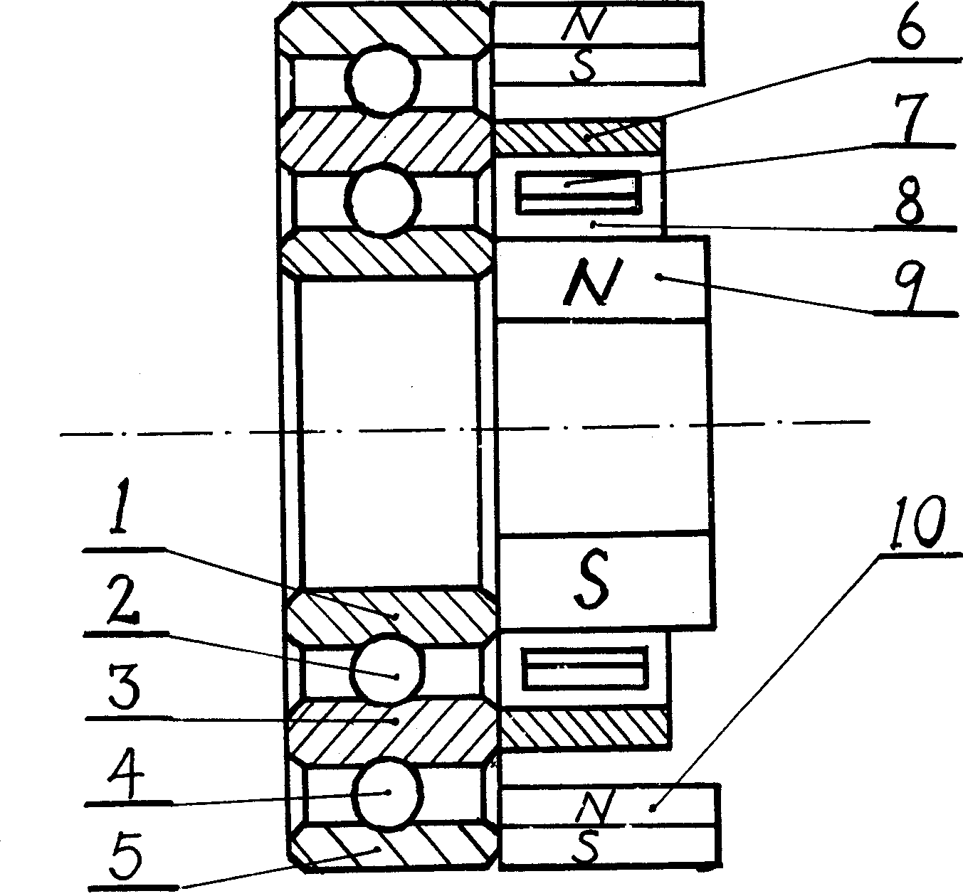
[0020] Please refer to the attached figure 1 .

[0021] Inner ring 1, balls 2, intermediate ring 3, balls 4, and outer ring 5 together form a two-stage radial ball bearing (cage diagram omitted). A permanent magnet 9 is fixedly installed on the right side of the inner ring 1 as an inner stator, so that the direction of the main magnetic pole of the magnet 9 is perpendicular to the axis of the bearing and intersects. On the right side of the middle ring 3, that is, on the same side as the inner stator, a consolidated cage-shaped hollow bronze ring 6 can be installed as a rotor. On the right side of the outer ring 5, a permanent magnet 10 is fixedly installed as an outer stator, so that the direction of the main magnetic pole of the magnet 10 is perpendicular to the axis of the bearing and intersects. Make the magnetic induction intensity of the inner and outer stators at the rotor place equal. Then the inner stator permanent magnet 9, the outer stator permanent magnet 10 and...


PUM


Abstract

A two-stage bearing using electromagnetically driven speed regulation between two stages is composed of an electromagnetically driven speed regulating mechanism and a two-stage bearing mechanism. It can increase the extreme rotation speed of whole bearing to maximum and decrease the relative rotation speed between two stages to minimum if it is used as a single-stage bearing for longer service life.

Description

[0001] The invention relates to a bearing, in particular to a secondary bearing with an electromagnetically driven speed regulating device capable of adjusting the rotating speed between stages. Background technique [0002] Citation: Chinese patent literature, publication number CN2122259U. [0003] A multi-layer radial ball bearing, compared with the existing radial ball bearing, is characterized in that: an intermediate ring is added between the inner and outer rings of the bearing, balls are installed between the inner ring and the intermediate ring of the bearing, and the outer ring and the intermediate ring of the bearing There are balls in between. The possibility of relative rotation between the inner and outer rings of the bearing is increased, so it can adapt to high-speed operation. [0004] It can be seen from the citations that the inner ring, the middle ring and the balls in between of this kind of secondary (ie two-layer) bearing form an ordinary single-stage b...

Claims


Application Information

Patent Timeline
Patent Type & Authority Applications(China)
IPC IPC(8): F16C32/04
CPCF16C19/55F16C33/306
Inventor 李军李康
Owner 李军
Why Eureka
Try Eureka