Flexible flat cable connecting method and boom structure of ultrasonic bonding machine

A flexible flat cable, ultrasonic welding technology, applied in the direction of connection, welding equipment, non-electric welding equipment, etc., can solve the problems of reducing the vibration energy of the conductive element 4 and the inability to achieve ultrasonic welding.

Inactive Publication Date: 2004-04-21
SUMITOMO WIRING SYST LTD
View PDF1 Cites 25 Cited by
  • Summary
  • Abstract
  • Description
  • Claims
  • Application Information

AI Technical Summary

Problems solved by technology

In this way, the vibrational energy transmitted to the conductive element 4

Method used


Image

  • Flexible flat cable connecting method and boom structure of ultrasonic bonding machine
  • Flexible flat cable connecting method and boom structure of ultrasonic bonding machine
  • Flexible flat cable connecting method and boom structure of ultrasonic bonding machine

Examples


Embodiment Construction

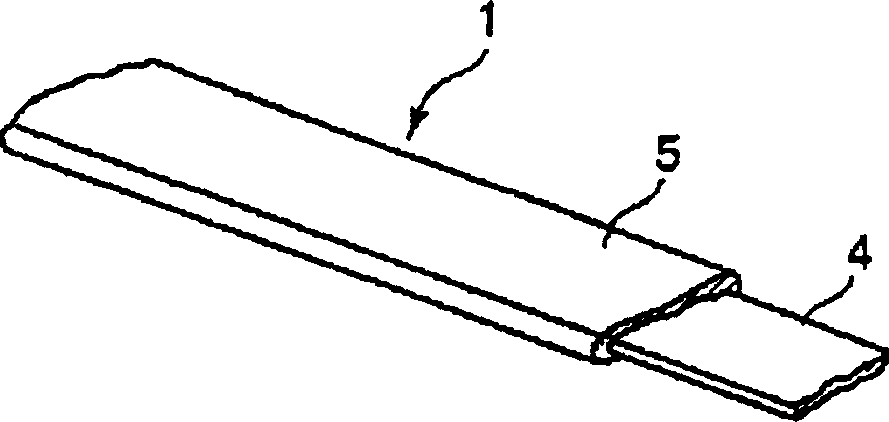
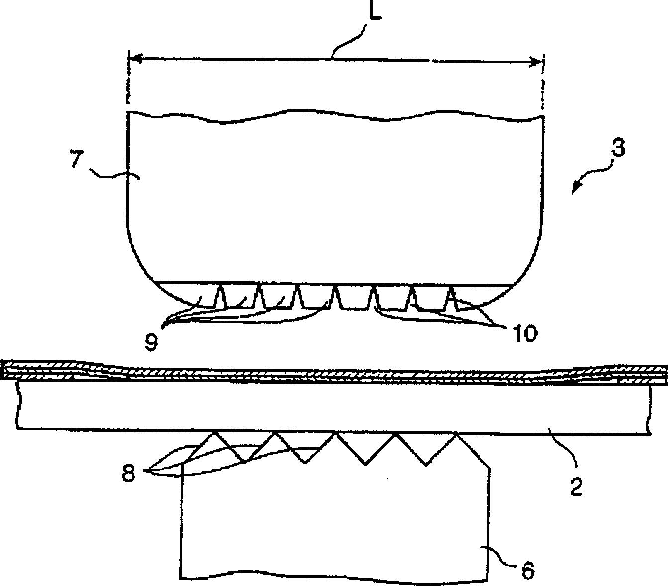
[0053] figure 1 A specific structure of the flexible flat cable 1 is shown, while Figure 2 to Figure 4 The basic structure of an ultrasonic welder 3 for connecting a flexible flat cable to an element to be connected, such as a busbar 2, is shown. Flexible flat cable 1, such as figure 1 As shown, a conductive element 4 made of copper foil having a thickness of 35 μm is covered by an insulating cover layer 5 made of, for example, PET (polyethylene terephthalate).

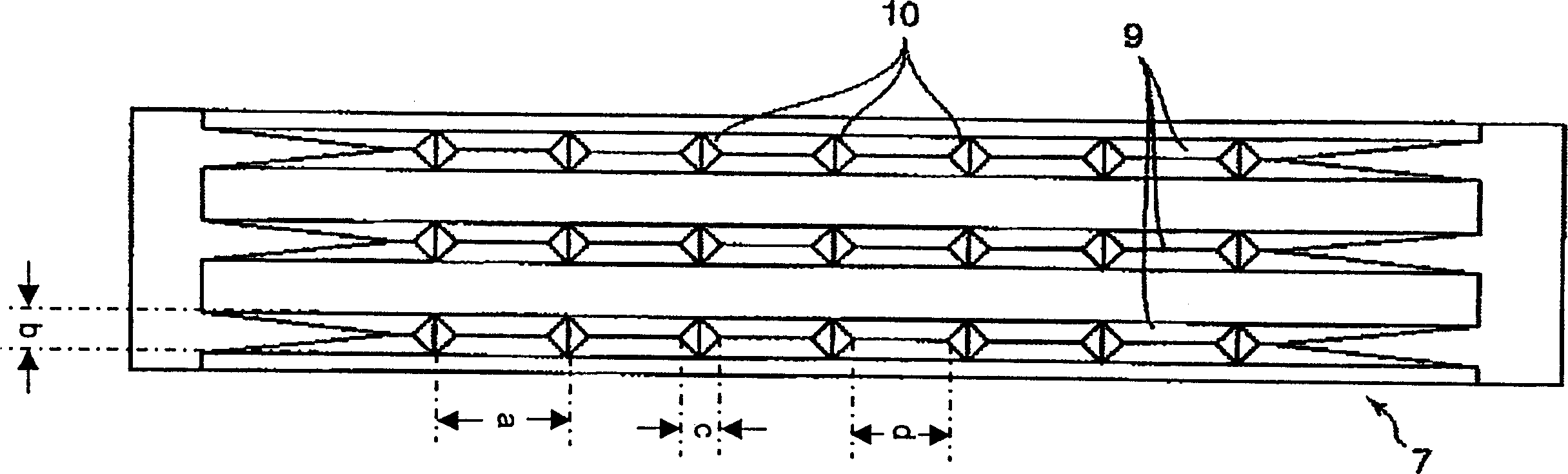
[0054] Such as figure 2 As shown, the ultrasonic welding machine 3 has an anvil 6 on which elements to be welded such as busbars 2 are placed, and an arm 7 for compressing the conductive element 4 of the flexible flat cable 1 and Busbar 2 is in contact. Tapering or converging protrusions 8 having a (preferably approximately right-angled) isosceles triangular cross-section are formed on the upper surface of the anvil 6 (the surface facing the bus bar 2 and / or the flexible flat cable 1), while the bus bar 2 On ...


PUM


Abstract

A flexible flat cable connecting method includes stripping an insulation coating (5) surface of a flexible flat cable (1) to be connected with a busbar (2) to expose a conductive element (4). The method continues by introducing the flexible flat cable (1) and the busbar (2) between a horn (7) and an anvil (6) of an ultrasonic welding machine (3), and then transmitting an ultrasonic vibration to the horn (7). The horn (7) has a plurality of elongated projections (9) of tapered cross-section pressed in contact with the insulation coating (5) of the flexible flat cable (1). Thus, the elongated projections (9) bite into the insulation coating (5) to weld the conductive element (4) ultrasonically into the busbar (2)

Description

technical field [0001] The invention relates to a method for connecting flexible flat cables with an ultrasonic welding machine and an arm structure of the ultrasonic welding machine. Background technique [0002] In the case of connecting a flexible flat cable to an element to be connected, such as a bus bar, wherein a conductive element, such as a copper foil having a thickness of about Covered with an insulating coating, usually using ultrasonic welding, in which the conductive elements are exposed by peeling off the insulating covering made of, for example, PET to a specified extent; the flexible flat cable and the elements to be connected are introduced into the ultrasonic welding machine between the anvil and the arm, while the exposed surface of the conductive element remains in contact with the upper surface of the element to be connected; ultrasonic vibration is applied to the arm while the flexible flat cable and the element to be connected are compressed, thereby ...

Claims


Application Information

Patent Timeline
IPC IPC(8): B23K20/10H01R43/00H01R43/02
CPCH01R43/0207B29C66/81433H01R12/592B29C66/83221B29C65/08B23K20/106B29C66/81417B29C66/81435B29C66/7392B29C66/41B29C66/45B29C66/71B29C66/1122B29K2705/10B29L2031/3462B29C66/81425B29K2067/003
Inventor 大石明典木原健
Owner SUMITOMO WIRING SYST LTD
Why Eureka
Try Eureka