Current sensor and overload current protective device comprising the same

A current sensor and current technology, applied in the direction of measuring current/voltage, voltage/current isolation, instruments, etc., can solve the problems of increasing system volume, large cost, and changes

Inactive Publication Date: 2004-04-21
FUJI ELECTRIC CO LTD
View PDF3 Cites 16 Cited by
  • Summary
  • Abstract
  • Description
  • Claims
  • Application Information

AI Technical Summary

Problems solved by technology

However, in this case, two types of coils are required, namely, a bias coil and a feedback coil, thus increasing the volume of the overall system
[0008] Moreover, when using the magneto-impedance element of the wire type and the film type, there is a problem that the sensitivity of the element depends on the material (permeability, resistivity, etc.) and the element size (length, film thickness, etc.) film width, etc.)
[0011] However, in order to reduce fluctuations in the sensitivity of components in the circuit, it is necessary to adjust and correct each system, which requires a large cost
Although each system can be tuned and corrected, automatic corrections cannot be achieved
Therefore, the output of the device varies with time, fluctuations in temperature, etc., resulting in a problem that high-precision compensation cannot be achieved

Method used


Image

  • Current sensor and overload current protective device comprising the same
  • Current sensor and overload current protective device comprising the same
  • Current sensor and overload current protective device comprising the same

Examples


Embodiment Construction

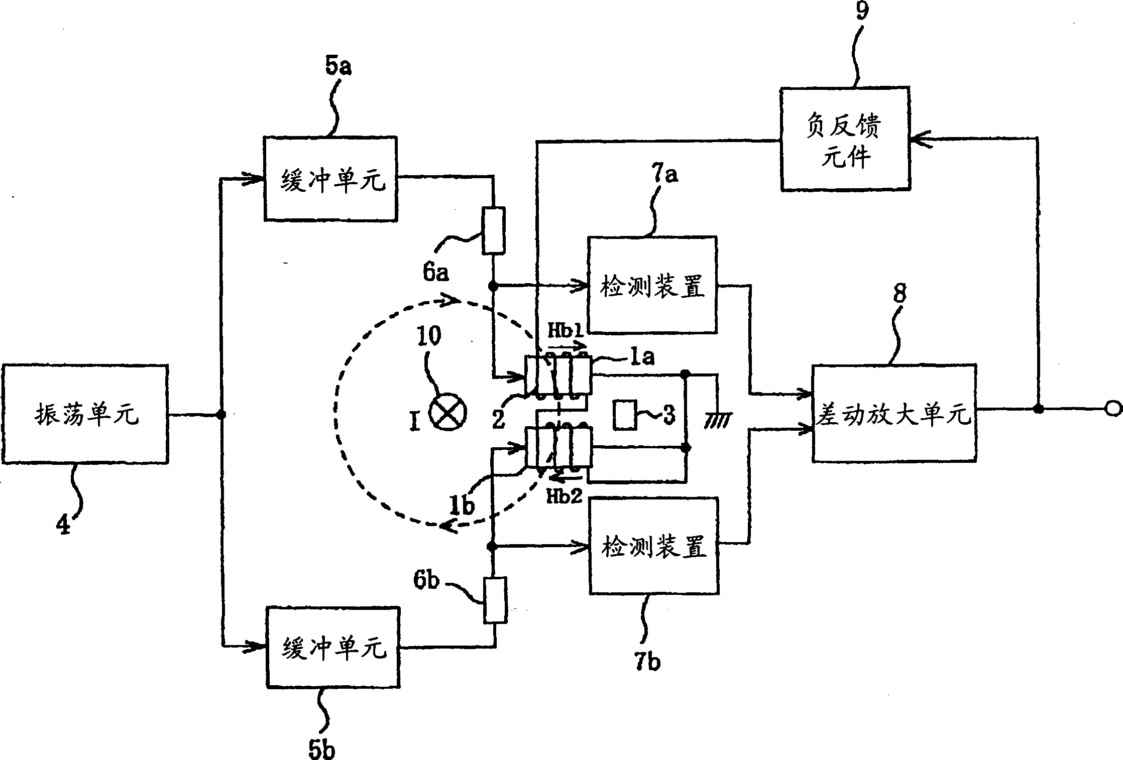
[0039] figure 1 The structure of the first embodiment of the present invention is shown.

[0040] exist figure 1 Among them, the magneto-impedance elements (also referred to simply as MI elements) 1a and 1b can be wire type or film type. Compensation coil 2 applies negative feedback to MI elements 1a and 1b. The magnet 3 applies a DC bias to the MI elements 1a and 1b. The oscillation unit 4 applies DC current to the MI elements 1a and 1b. The buffer units 5 a and 5 b are inserted according to the current level output by the oscillator 4 . Reference numerals 6a and 6b denote resistors. The detection means 7a and 7b detect the variation of the alternating current as a function of the external magnetic field applied to the MI elements 1a and 1b. The differential amplification unit 8 amplifies the output difference of the detection unit. Negative feedback element 9 supplies current to compensation coil 2 according to the output of differential amplification unit 8 . The ...


PUM


Abstract

A small, low-cost, wide-range current sensor excellent in environmental resistance and noise resistance and high in accuracy, and an application device, a DC magnetic field is applied to two magnetic elements (1a, 1b) having a magnetic impedance effect by means of a magnet (3), while a negative feedback magnetic field is applied to both elements by means of a coil (2). The variation of the magnetic field depending on the external magnetic field applied to the magnetic elements (1a, 1b) is detected by detection units (7a, 7b). The difference between the output is amplified by a differential amplifier unit (8). Thus, detection is achieved in a wide range while eliminating the influence of the noise.

Description

technical field [0001] The present invention relates to a current sensor using a magnetic element with a magneto-impedance effect and an overload current protection device using the current sensor. Background technique [0002] Traditionally, current transformers are widely used as current sensors, but due to their low sensitivity, laminated iron cores are required, and the iron cores will be magnetically saturated, thus causing the problem of insufficient current detection range. Iron cores can also cause problems with larger sensor units. [0003] On the other hand, there is a method that uses a Hall element and a magnetoresistive element as a current detection element. However, because of their low detection sensitivity, polymagnetic cores and Hall elements, or magnetic elements mounted in the grooves of the polymagnetic cores, are usually provided to increase sensitivity. [0004] Like current transformers, the above-mentioned method of using a polymagnetic core requir...

Claims


Application Information

Patent Timeline
Patent Type & Authority Applications(China)
IPC IPC(8): G01R33/02G01R15/14G01R15/18G01R15/20G01R19/165G01R33/028
CPCG01R15/148G01R15/18
Inventor 工藤高裕北出雄二郎石川公忠
Owner FUJI ELECTRIC CO LTD
Why Eureka
Try Eureka