Digital control working machine with grinder

A grinding device and processing machine technology, applied in metal processing machinery parts, feeding devices, metal processing and other directions, can solve the problems of lower product qualification rate, prolonged processing time, inconsistent product specifications, etc., to reduce inertial force and improve followability , light weight effect

Inactive Publication Date: 2004-04-28
WEST ELECTRIC CO LTD
View PDF5 Cites 17 Cited by
  • Summary
  • Abstract
  • Description
  • Claims
  • Application Information

AI Technical Summary

Problems solved by technology

This is because the machining of the shape of the workpiece and the machining of the surface accuracy (surface finish), that is, grinding, are different and cannot be performed with the same device at present.
Therefore, after the workpiece is shaped by the shaping machine, the workpiece must be removed from the shaping machine and mounted on the finishing machine, and the workpiece may be moved between the machining machines. The problem that the pass rate decreases due to loading and unloading processing
[0011] In addition, it is necessary to reset the workpiece to another processing machine. Therefore, for example, it is difficult to align the axis of the workpiece with the rotation axis of the processing machine with high precision, and resetting the workpiece to the processing machine is also a major cause of defective products. reason
That is, in the process of forming the shape of the workpiece and the process of surface precision (surface finish) processing, in order to avoid the situation that the processed shape of the workpiece is not completely consistent, in the process of surface precision processing in the subsequent process, it is necessary to process Including the amount of setting error, while prolonging the processing time, there will be some deviation between the predetermined processing shape and the processed processing shape, which will cause the product to be inconsistent with the final specification, resulting in the qualified product rate reduction

Method used


Image

  • Digital control working machine with grinder
  • Digital control working machine with grinder
  • Digital control working machine with grinder

Examples


Embodiment Construction

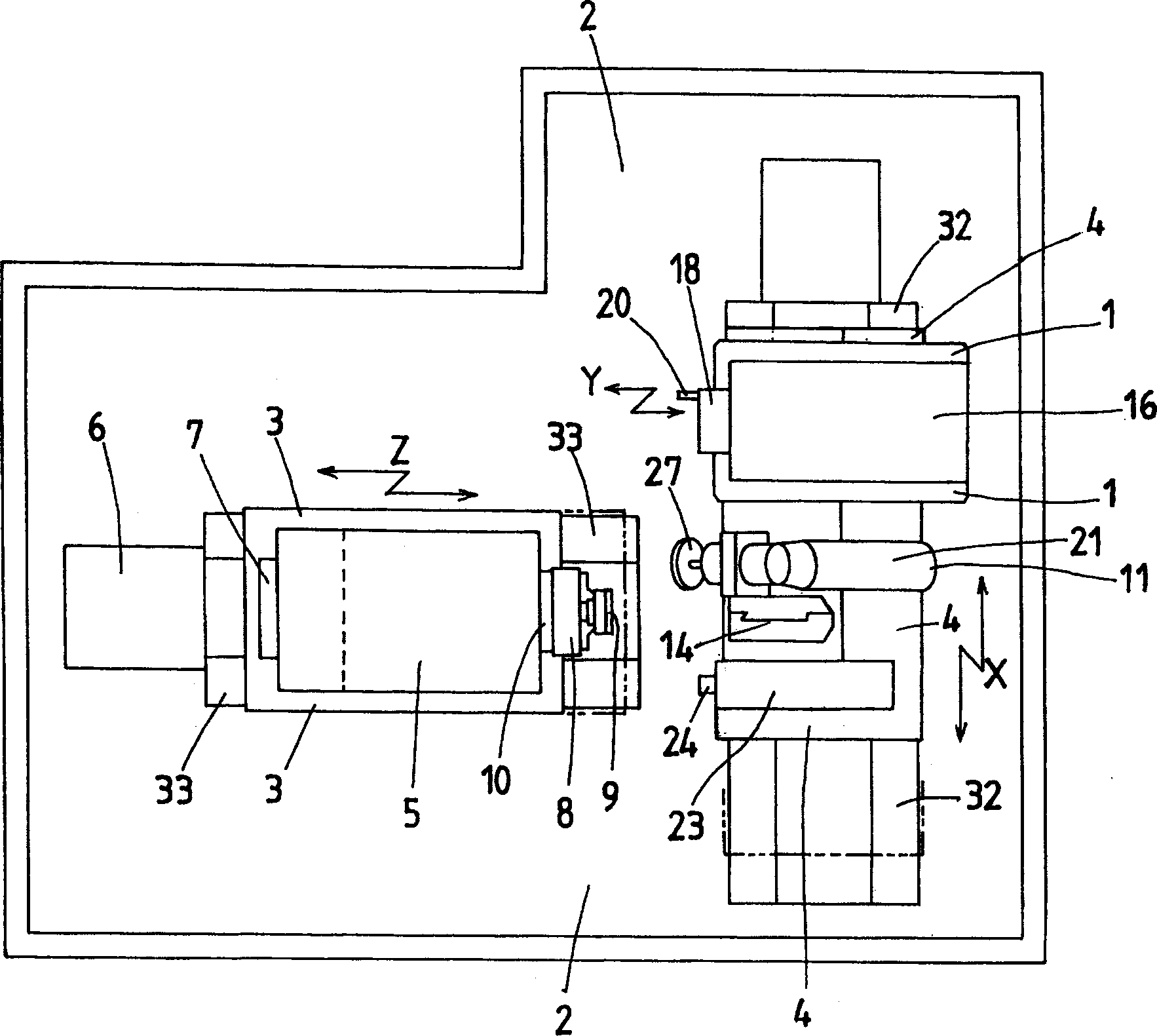
[0031] Hereinafter, an embodiment of a numerical control (NC) processing machine with a grinding device according to the present invention will be described with reference to the drawings. In addition, the NC processing machine with a grinding device according to the present invention is compatible with Figure 4 Compared with the NC processing machine shown, since the main shaft, the Z-axis table that can move in the Z-axis direction, and the X-axis table that can move in the X-axis direction correspond to each other, the same numbers are used for these parts Be explained.

[0032] Such an NC processing machine with a grinding device, for example, includes: a Z-axis table 3, on a Z-axis base 33 provided on the base 2 of the processing machine, which can move along the Z-axis direction as the longitudinal direction of the spindle 10; and X The axis worktable 4 is provided separately from the Z axis worktable 3, and can move along the X axis direction perpendicular to the Z axis on...


PUM


Abstract

The NC processing machine has the Y-axial cutting tool mounted on a slider which is arranged in a sliding base on a X-axial table and reciprocates in the Y-axial direction. This NC processing machine cuts the work into the prescribed processing configuration with the Y-axial cutting tool while the slider is reciprocating in synchronism with rotation of a main shaft 10, and then polishes a processing surface of the work by a buff of the polishing unit in accordance with configuration of a program surface of the work without change in a grasping state of the work with a chuck device .

Description

Technical field [0001] The present invention relates to, for example, a Y-axis cutting tool provided on a sliding member that reciprocates with respect to a spindle holding a workpiece, so that the sliding member reciprocates at high speed and acceleration in synchronization with the rotation of the spindle to perform cutting processing on the workpiece. A numerical control (NC) processing machine with a grinding device that then uses a grinding device to grind the processed surface of the workpiece after cutting. Background technique [0002] In the prior art, there is known a mounting device for mounting a grinder on a lathe. The lathe can directly perform grinding without removing the turned workpiece from the chuck of the spindle. A transverse feed table is provided on the reciprocating table on the base of the lathe equipped with a feed control device. A tool holder is installed on the side of the horizontal top surface of the infeed table close to the human body, and on the...

Claims


Application Information

Patent Timeline
Patent Type & Authority Applications(China)
IPC IPC(8): B23B5/00B23P23/02B23Q15/00
CPCB23P23/02G05B2219/45156B23B5/00B23Q15/00Y10T29/511Y10T29/5146Y10T29/5168Y10T29/5171Y10T29/5172Y10T29/5173Y10T29/5175
Inventor 新贝幸树森川敏郎
Owner WEST ELECTRIC CO LTD
Why Eureka
Try Eureka