Processing method of lighter electronic striking head and its special mould

A processing method and lighter technology, applied in the direction of combustion method, combustion ignition, lighting and heating equipment, etc., can solve the problems of low production efficiency, high scrap rate, troublesome head-shot processing, etc., achieve high production efficiency, control production cost, The effect of simple structure

Inactive Publication Date: 2004-05-05
项龙江
View PDF0 Cites 3 Cited by
  • Summary
  • Abstract
  • Description
  • Claims
  • Application Information

AI Technical Summary

Problems solved by technology

[0002] The electronic head of lighters is an indispensable part of electronic ignition lighters. Since the production of lighters has formed a large-scale model with a very fine social division of labor in Wenzhou, my country, the electronic head of a lighter as large as a grain of rice is produced by many Manufacturers specialize in manufacturing and the competition is fierce. Whoever is one step ahead in terms of product quality and cost will be in a very favorable competitive position. The electronic head of the lighter is mainly composed of two parts: a stepped shaft and a guide shaft. The existing electronic head of the lighter is in the patent No. There are detailed introductions in the patent specifications of 95244243 and 4, wherein the split lighter electronic head is as figure 1 As shown, it is composed of a stepped shaft 1 and a guide shaft 2, the guide shaft 2 is arranged orthogonally to the stepped shaft 1, wherein the stepped shaft 1 has a through hole orthogonal to its central axis for arranging the guide shaft 2, An interference fit is adopted between the guide shaft 2 and the stepped shaft 1, which is cumbersome to process, has low production efficiency, and high scrap rate; figure 2 As shown, it contains a stepped shaft 1, a guide shaft 2, and the guide shaft 2 is arranged orthogonally to the stepped shaft 1. The head is an integral structure processed by cold extrusion. As an inseparable whole, this kind of head is formed by cold extrusion processing at one time, and the production efficiency is quite high. However, if this kind of head is made of softer materials, the strength of the head product is not enough, it is easy to deform and fail, and its life is too short , if a harder material is used, the extrusion or stamping die will be easily damaged, the production cost will be significantly increased, and the product will not have price competitiveness in the market

Method used


Image

  • Processing method of lighter electronic striking head and its special mould
  • Processing method of lighter electronic striking head and its special mould
  • Processing method of lighter electronic striking head and its special mould

Examples


Embodiment Construction

[0017] Below in conjunction with accompanying drawing and embodiment the present invention is described in further detail:

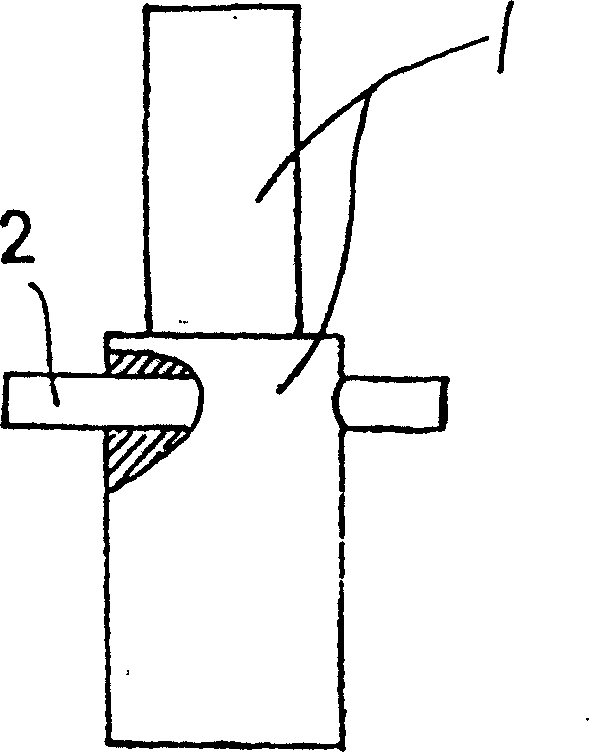
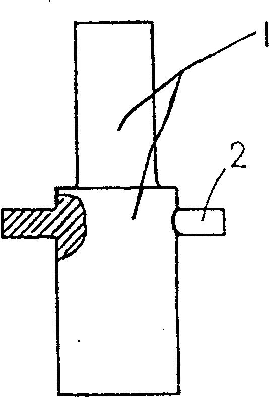
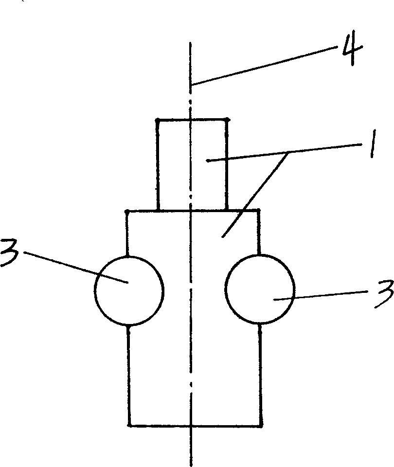
[0018] In each drawing: 1. Step shaft; 2. Guide shaft; 3. Flat lug; 4. Step shaft axis; 5. Left half mold; 6. Right half mold; 7. Limiting insert; 8. Half cylinder hole Groove; 9, punching flat shaft; 10, mating surface; 11, limit groove; 12, punching head perforation.

[0019] Such as image 3 , Figure 4 , Figure 5 As shown, in order to overcome the disadvantage that the processing guide shaft of the mold is easily damaged when cold extrusion processing the electronic head of the lighter in the past, in the process of processing, the guide shaft 2 of the electronic head of the lighter is partially punched and flattened as shown image 3 , Figure 4 state, forming two symmetrical flat ears 3, a part of each flat ear 3 is located on the inner side of the cylindrical surface of the cylindrical blank, and the other part is located on the outer side of...


PUM


Abstract

A technology for machining the electric firing head of lighter includes forming the guide axle through punching the part of the raw cylindrical material for flattening it to become symmetrical flat ears and punching the flat ears upward and downward to obtain the guide axle, and forming the stepped axle. A special die is also disclosed. Its advantages are high productivity, low cost and long service life of product.

Description

technical field [0001] The invention relates to a processing method of an electronic striker in a piezoelectric ignition device of a lighter and a special mold thereof. Background technique [0002] The electronic head of lighters is an indispensable part of electronic ignition lighters. Since the production of lighters has formed a large-scale model with a very fine social division of labor in Wenzhou, my country, the electronic head of a lighter as large as a grain of rice is produced by many Manufacturers specialize in manufacturing and the competition is fierce. Whoever is one step ahead in terms of product quality and cost will be in a very favorable competitive position. The electronic head of the lighter is mainly composed of two parts: a stepped shaft and a guide shaft. The existing electronic head of the lighter is in the patent No. There are detailed introductions in the patent specifications of 95244243 and 4, wherein the split lighter elec...

Claims


Application Information

Patent Timeline
IPC IPC(8): F23Q2/28F23Q2/34
Inventor 项龙江
Owner 项龙江
Why Eureka
Try Eureka