

Tool carriage for composite needle and transferring component
A tool and knitting technology, applied in furnace components, conveyor objects, knitting, etc., can solve the problem of high price, and achieve the effect of low transportation weight and easy formation
- Summary
- Abstract
- Description
- Claims
- Application Information
AI Technical Summary
Problems solved by technology
Method used
Image

Examples
Embodiment Construction
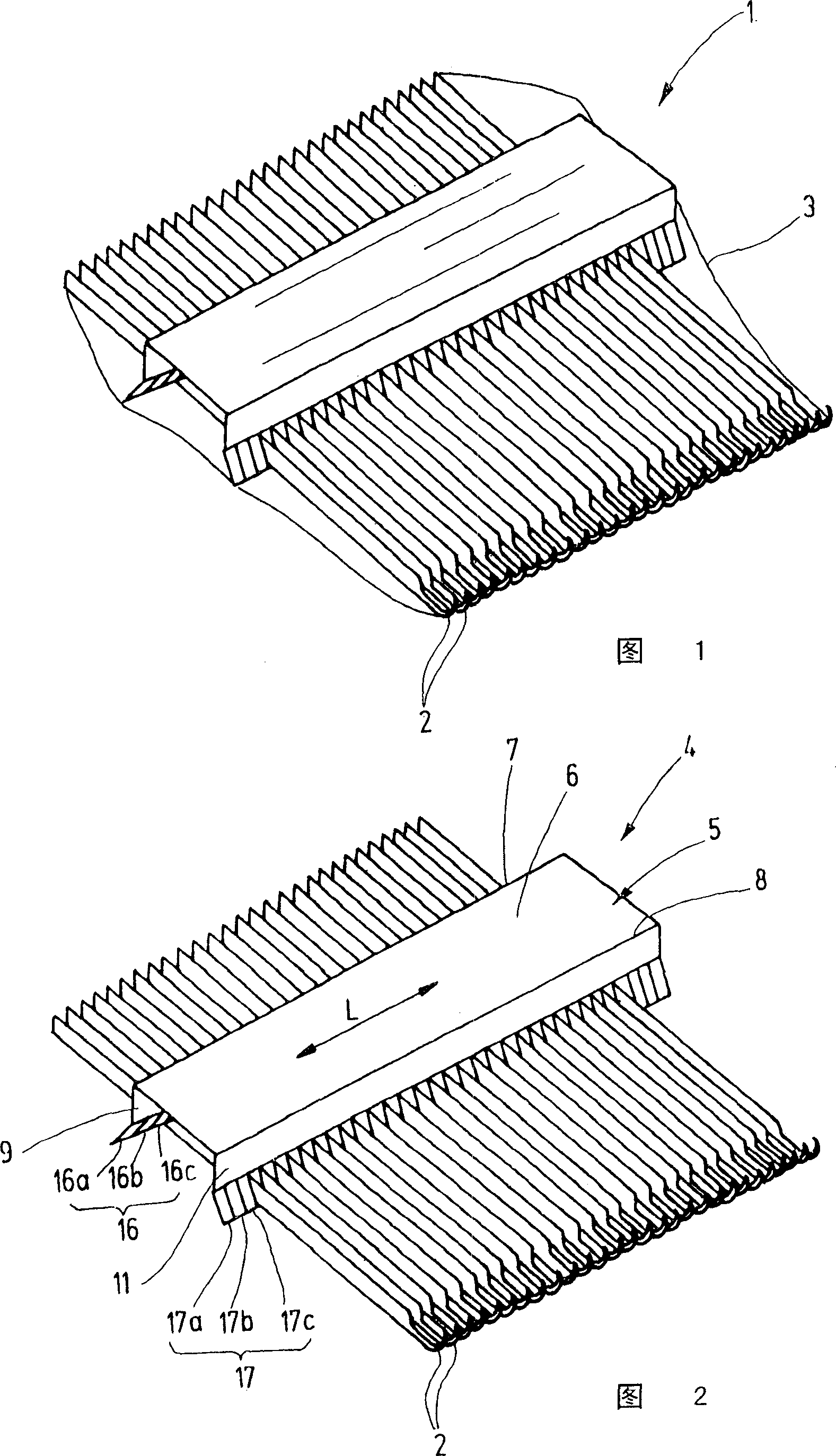
[0023] Figure 1 shows a dispatchable pack 1 with a knitting tool 2 having multiple parts detachably connected. The transmitting unit 1 is provided with a sheath 3 which can be designed to be rigid or flexible. Oiled paper, plastic film, shrinkable plastic film, a folding box, a plastic box, etc. can be used as the foreskin. In the inner cavity of the foreskin 3 is placed the knitting tool 2, which is held by a tool holder as shown in FIG. 2 .
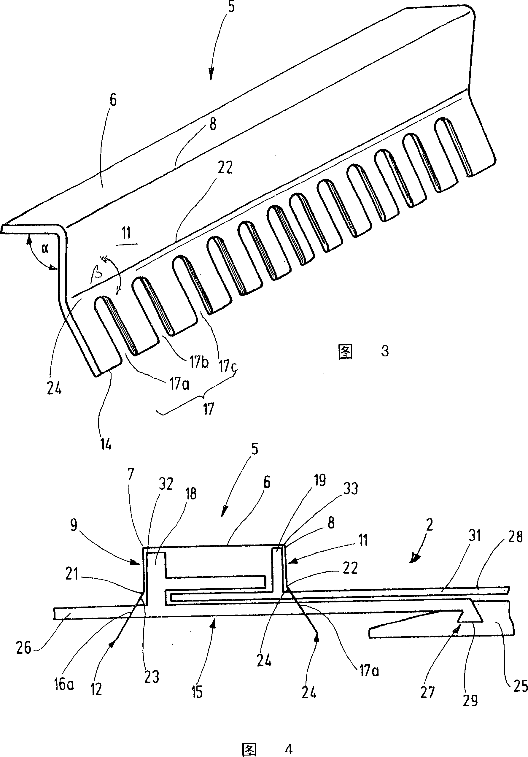
[0024] The tool carrier 4, in the embodiment described above, consists of a transport rail 5 supporting individual knitting tools. The transport rail 5 is, for example, an integral plastic profile, as shown in FIG. 3 , preferably designed to have a uniform wall thickness. There is a strip-shaped back section 6 extending in the longitudinal direction L with two long mutually parallel sides 7 , 8 which are sharp or rounded. The sides 7 , 8 are marked by bend lines at which the back section 6 transitions into the clamping legs 9 , 11 co...
PUM
 Abstract
Description
Claims
Application Information