Fibre bundle buncher for spinning machine

A bundling device and a fiber bundle technology are applied in the field of fiber bundle bundling devices, which can solve the problems of increased cost, troublesome replacement of breathable aprons, and a large amount of time to replace, and achieve the effect of simplifying the structure

Inactive Publication Date: 2004-05-12
TOYOTA IND CORP
View PDF2 Cites 4 Cited by
  • Summary
  • Abstract
  • Description
  • Claims
  • Application Information

AI Technical Summary

Problems solved by technology

However, in the structure in which an adjustment element is also provided in addition to the suction pipe and the winding element, the replacement of the air-permeable apron is quite cumbersome because the cooperation between the winding element and the adjustment element needs to be loosened during replacement. Therefore need a large amount of time to replace hundreds or even thousands of such air-permeable aprons arranged on each spinning machine
In addition, the structure disclosed in Patent Document 3 leads to an increase in cost, which is designed to perform special processing on the rotating shaft

Method used


Image

  • Fibre bundle buncher for spinning machine
  • Fibre bundle buncher for spinning machine
  • Fibre bundle buncher for spinning machine

Examples


Embodiment Construction

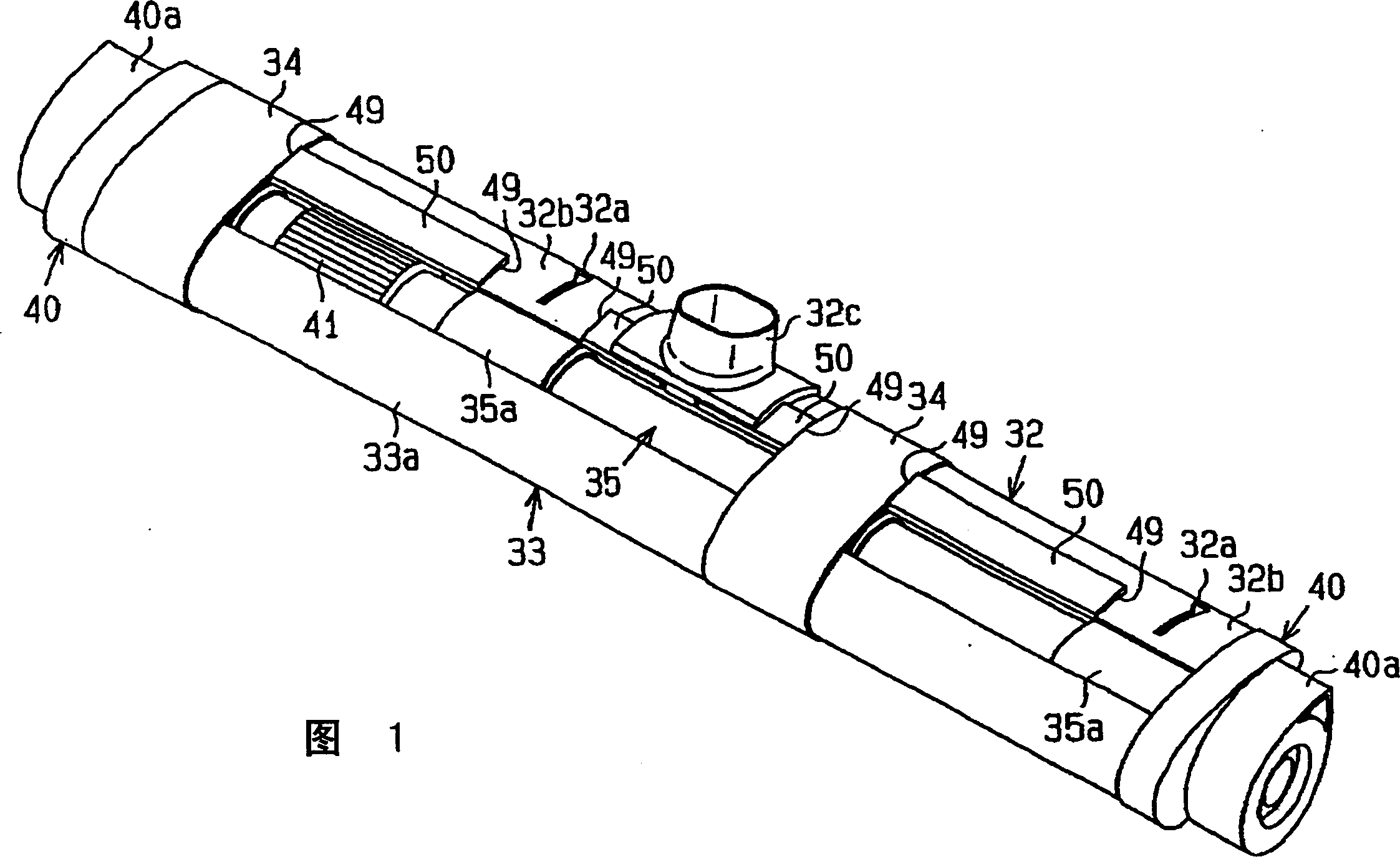
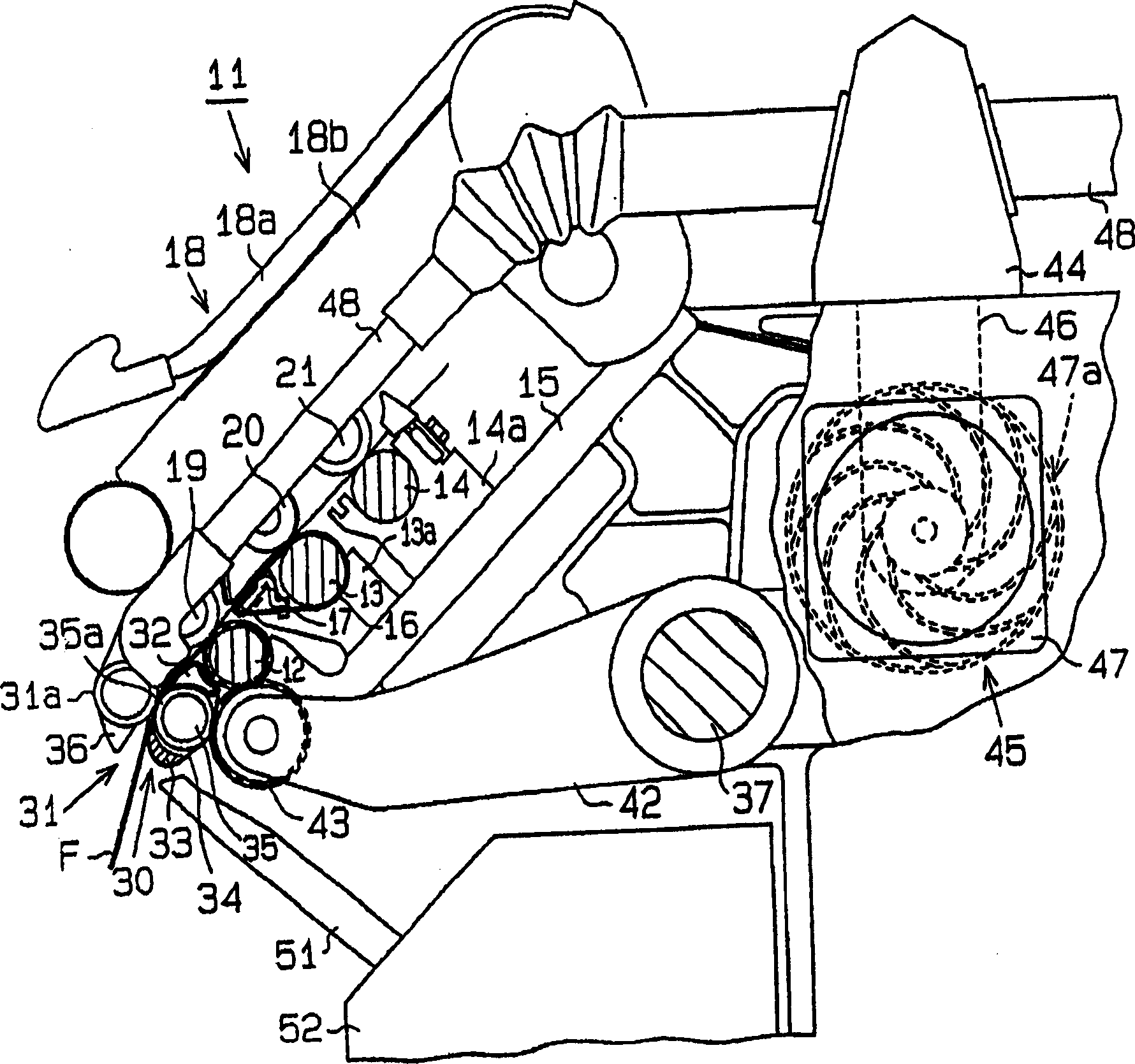
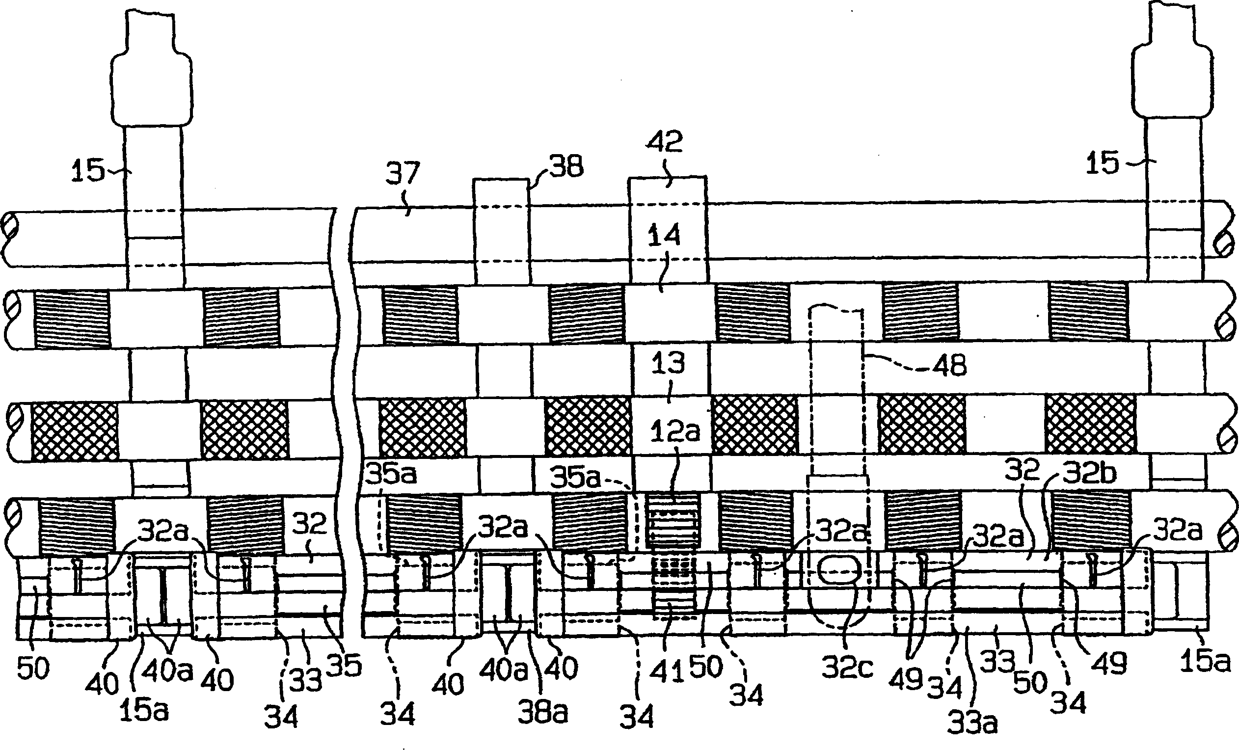
[0022] An embodiment of the present invention will now be described with reference to FIGS. 1-6. Fig. 1 is a schematic perspective view of a unit equipped with a suction tube, a winding element, breathable aprons and the like. figure 2 is a partial side view in section showing one side of a drafting unit and a fiber bundle bundling unit. image 3 It is a partial schematic view omitting the top roller side, showing the relationship between the bottom roller of the drafting device and the suction portion of the fiber bundle concentrating device, and the bottom nip roller. Figure 4A is a schematic view of the fiber bundle bundling device at a nip point as seen in the fiber bundle drawing direction (viewed from the front side with respect to the fiber bundle moving direction in the drafting device).

[0023] Such as figure 2 As shown, a drafting unit 11 as a drafting section is a 3-row structure equipped with front bottom rollers 12 , middle bottom rollers 13 and rear bottom ro...


PUM


Abstract

A fiber bundle collecting device is provided on the downstream side of a final delivery roller pair of a drafting device and includes a delivery portion and a suction pipe 32 having a sliding surface 32b that is equipped with a suction hole 32a provided on the upstream side of the nip point of the delivery portion with respect to a direction in which a fiber bundle moves. A wrapping member 33 is provided on the side opposite to the suction pipe 32 across a bottom nip roller 35a constituting the delivery portion. An air-permeable apron 34 is wrapped around the suction pipe 32, the wrapping member 33, and the bottom nip roller 35a. A regulating guide 49 for preventing lateral displacement of the air-permeable apron 34 is formed integrally with the suction pipe 32. The regulating guide 49 is formed by removing a part of an elevated step portion 50 in conformity with the width of the air-permeable apron 34, the step portion 50 being formed on the front side of the top surface of the suction pipe 32 so as to extend in a longitudinal direction.

Description

technical field [0001] The present invention relates to a fiber bundle bundling device of a spinning machine, and more particularly to a fiber bundle converging device provided, for example, on the downstream side of a drafting device (drafting section) of a spinning machine and adapted to collect fibers produced by the drafting device. Fiber bundle bundling device for drawn fiber bundles. Background technique [0002] A variety of fiber bundle bundle devices have been proposed for the purpose of achieving improvements in yarn quality, such as reducing the generation of fuzz by collecting the drawn fiber bundles before they are subjected to twisting. An endless perforated belt (perforated apron) is typically used for the collection and delivery of a fiber bundle for the basic functions of these devices. [0003] For example, refer to the descriptions in paragraphs 0022, 0030 and accompanying drawings 1 and 7 of Japanese Patent Laid-Open No. 11-286837 as Patent Document 1. ...

Claims


Application Information

Patent Timeline
Patent Type & Authority Applications(China)
IPC IPC(8): D01H5/72D01H1/02D01H5/26D01H5/86
CPCD01H13/16
Inventor 新美究中野勉河合泰之
Owner TOYOTA IND CORP
Why Eureka
Try Eureka