
Fixed constant-velocity universal joint body and its manufacturing method

A constant-velocity universal joint with uniform circumferential distribution technology, which is applied to rotating parts that resist centrifugal force, elastic couplings, mechanical equipment, etc. It can solve the problems of reduced assembly and difficulty in pushing the inner ring of the joint, and achieves simplified assembly. Effect

Inactive Publication Date: 2004-05-19
NTN CORP
View PDF2 Cites 9 Cited by
  • Summary
  • Abstract
  • Description
  • Claims
  • Application Information

AI Technical Summary

Problems solved by technology

However, if it is applied to a UJ type constant velocity universal joint, the track groove of the joint inner ring of the UJ type constant velocity universal joint has a flat bottom, and since this flat bottom is located at the insertion end of the joint inner ring, the joint The straight portion of the track groove on the inner ring is large relative to the inner diameter of the retainer, which has embedded balls in its dimples and is supported by the outer ring of the joint, making it difficult to push the inner ring of the joint, reducing the its assembly

Method used


Image

  • Fixed constant-velocity universal joint body and its manufacturing method
  • Fixed constant-velocity universal joint body and its manufacturing method
  • Fixed constant-velocity universal joint body and its manufacturing method

Examples


Embodiment Construction

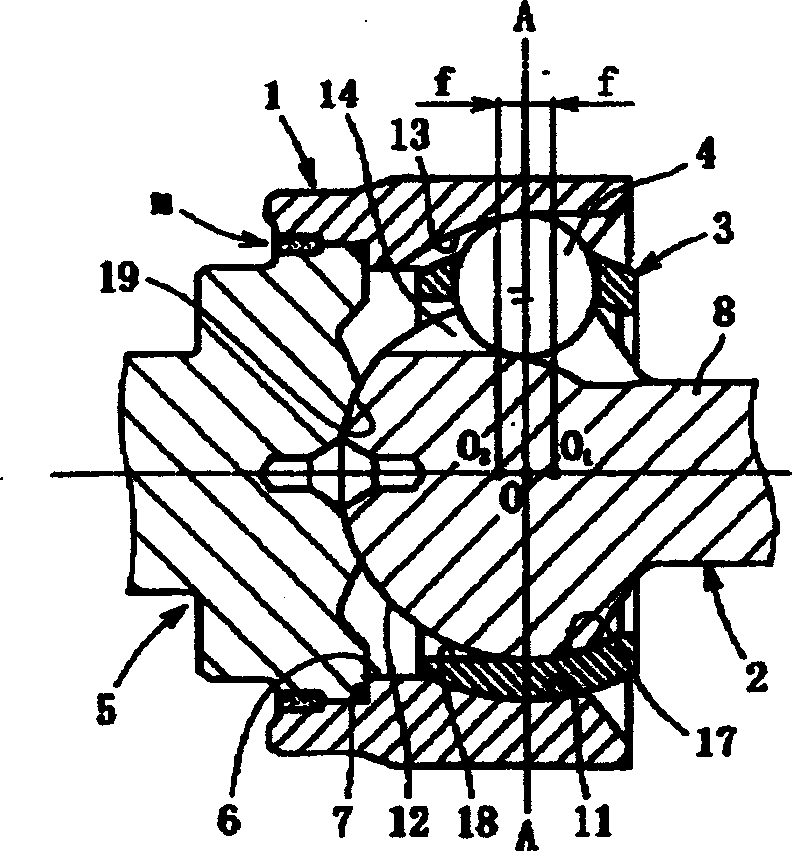
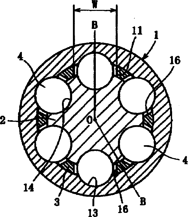
[0039] Figure 1 (a) and Figure 1 (b) show an embodiment of the present invention, which is a UJ-type fixed constant velocity universal joint, where Figure (a) is taken along the line BOB in Figure (b) Open sectional view, Figure (b) is a sectional view taken along the AOA line in Figure (a). The fixed type constant velocity universal joint in this embodiment includes a joint outer ring 1, a joint inner ring 2, a retainer 3, a torque transmission ball 4 (hereinafter referred to as a ball), and a shaft 5.

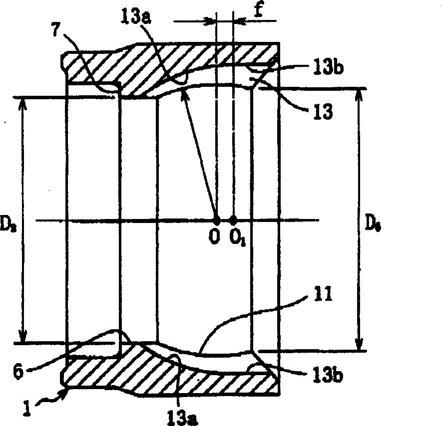
[0040] Such as figure 2 As shown, the joint outer ring 1 is in the shape of a sleeve, one end of which is open for inserting the shaft 5, and the other end is open for receiving the joint inner ring 2, the retainer 3 and the ball 4. One end surface (rod side) of the outer ring 1 of the joint is formed by the inner cylindrical surface 6, and the smallest inner diameter D of the inner cylindrical surface 2 Greater than the outer diameter D of the inner ring 2 of the joint 1 , In o...


PUM


Abstract

A fixed type constant velocity joint includes a cylindrical joint outer ring having an inner spherical surface formed with circumferentially equispaced axially extending track grooves, a joint inner ring having an outer spherical surface formed with circumferentially equispaced axially extending track grooves, balls disposed in ball tracks defined by cooperation between the track grooves in the joint outer and inner rings, and a cage for holding the balls in the ball tracks. The rear open end of the joint outer ring has an inner diameter larger than the outer diameter of the joint inner ring, an inner diameter surface of said cage is a surface having a shape such that the region located forwardly of the axial center is capable of controlling the forward movement of the joint inner ring while the region located rearwardly of the axial center is capable of allowing the axial movement of the joint inner ring.

Description

Technical field [0001] The invention relates to a fixed type constant velocity universal joint used in energy transmission systems of automobiles and various industrial equipment, for example, suitable for the situation where only the working angular displacement is allowed between two driving shafts and a driven shaft. Background technique [0002] Fixed type constant velocity universal joints are available, for example, UJ type (lower part free cutting). The structure of this fixed type constant velocity universal joint includes a joint outer ring with an inner spherical surface, a plurality of circumferentially uniformly distributed axially extending track grooves on the inner spherical surface; a joint inner ring with an outer spherical surface, and a circumferential uniform surface on the outer spherical surface. The axially extending track groove of the cloth, the track groove exactly corresponds to the track groove on the outer ring of the joint; a plurality of balls are p...

Claims


Application Information

Patent Timeline
Patent Type & Authority Applications(China)
IPC IPC(8): F16D3/20F16D3/2237F16D3/2245
CPCF16D3/2233F16D2003/22313F16D2003/2232F16D2003/22303Y10S464/906F16D3/2237F16D3/2245F16D3/20
Inventor 曾根启助中小路雅文
Owner NTN CORP
Learn More