Droplet ejecting device and method thereof

A droplet and liquid technology, which is applied in liquid injection devices, injection devices, lighting devices, etc., can solve problems such as poor ejection and complex circuit structure, and achieve the effect of suppressing temperature changes

Inactive Publication Date: 2004-05-26
SEIKO EPSON CORP
View PDF1 Cites 7 Cited by
  • Summary
  • Abstract
  • Description
  • Claims
  • Application Information

AI Technical Summary

Problems solved by technology

However, in the prior art described above, since the head drive signal generating unit and the heating signal generating unit are provided separately, the circuit configuration becomes complicated, and since the heating signal is applied to the piezoelectric element (piezoelectric element ), so when the ink is

Method used


Image

  • Droplet ejecting device and method thereof
  • Droplet ejecting device and method thereof
  • Droplet ejecting device and method thereof

Examples


Embodiment Construction

[0040] Hereinafter, an embodiment of the droplet ejection device and method of the present invention will be described with reference to the drawings.

[0041] [The overall structure of the droplet ejection device]

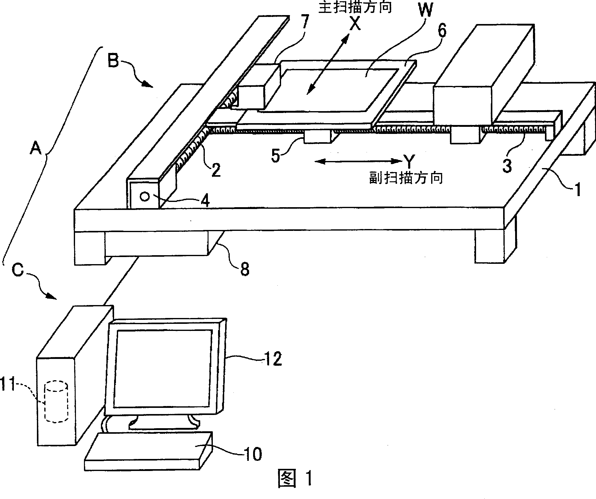
[0042] FIG. 1 is a perspective view showing the overall structure of the droplet ejection device of this embodiment. As shown in this FIG. 1, the present droplet ejection device A is composed of a main body B and a control computer C. The main body B is composed of the base 1, the X-direction drive shaft 2, the Y-direction drive shaft 3, the X-direction drive motor 4, the Y-direction drive motor 5, the table 6, the ejection head 7, and the control device 8. On the other hand, the control computer C includes a keyboard 10, an external storage unit 11, a display unit 12, and the like.

[0043] The base 1 is a square flat plate having a predetermined area, and an X-direction drive shaft 2 and a Y-direction drive shaft 3 arranged perpendicular to each other are provided o...


PUM


Abstract

To rapidly heat a liquid for discharge by heating of a piezoelectric element. In a device which discharges the liquid for discharge as liquid droplets from an opening by mechanically deforming the piezoelectric element by a normal drive signal, a drive signal for heating which prevents liquid droplets from being discharged from the opening and has a repetition frequency of an ultrasonic wave band is applied to the piezoelectric element.

Description

Technical field [0001] The present invention relates to a droplet ejection device and method for ejecting droplets to an object using a piezoelectric element. Background technique [0002] Japanese Patent Laid-Open No. 11-138798 discloses an inkjet printer as an application example of a droplet ejection device. The inkjet printer applies a heating signal dedicated to heating to a piezoelectric element (piezoelectric element), and the ink is heated by the heat of the piezoelectric unit to reach an appropriate temperature. According to the inkjet printer, the ink can be heated without a complicated head structure, and the bad influence of the ink viscosity change caused by the temperature change on the drawing can be avoided. [0003] In the above-mentioned inkjet printer, the repetition frequency of the heating signal is set higher than the resonance frequency of the head, so that ink cannot be ejected from the head, or when the repetition frequency is set near the resonance frequ...

Claims


Application Information

Patent Timeline
IPC IPC(8): B05B17/06B41J2/045B41J2/055G02B5/20H01L51/50H05B33/10
CPCB41J2/04563B41J2/04581B41J2/04588B41J2/04528B41J2/045
Inventor 臼田秀范
Owner SEIKO EPSON CORP
Why Eureka
Try Eureka