Stacker for plate members, method for stacking plate members, and stacked plate members

A technology for stacking machines and panels, which is applied in the field of stacking machines, and can solve problems such as easy deformation of inner heat sinks, difficulty in placement, deformation of inner heat sinks, etc.

Inactive Publication Date: 2004-05-26
SHOWA DENKO KK
View PDF1 Cites 2 Cited by
  • Summary
  • Abstract
  • Description
  • Claims
  • Application Information

AI Technical Summary

Problems solved by technology

[0007] In the former stacker that stacks panels by letting them fall naturally, there is such a problem that the impact at the time of falling may deform the inner fins because the inner fins are thin and thus easily deformed
Also, since the inner fins are thin and usually made of aluminum or an aluminum alloy, and are therefore very light, the drop rate is low, which in turn slows down the buildup rate
Also, since the inner fins are made with a wavy cross-section, it is difficult to determine the direction of their fall, which makes it difficult to place them neatly
[0008] On the other hand, in the latter stacker using cam stacking plates, since the inner fins are positioned one by one, the stacking rate is low.
In addition, since the inner fin is easily deformed due to its thin thickness, the cam causes deformation of the inner fin
[0009] Also, since the oil-free inner fins are difficult to slide over each other, it can be difficult to stack them neatly

Method used


Image

  • Stacker for plate members, method for stacking plate members, and stacked plate members
  • Stacker for plate members, method for stacking plate members, and stacked plate members
  • Stacker for plate members, method for stacking plate members, and stacked plate members

Examples


Embodiment Construction

[0043] The best way to practice the invention

[0044] The present invention will be described below with reference to the accompanying drawings.

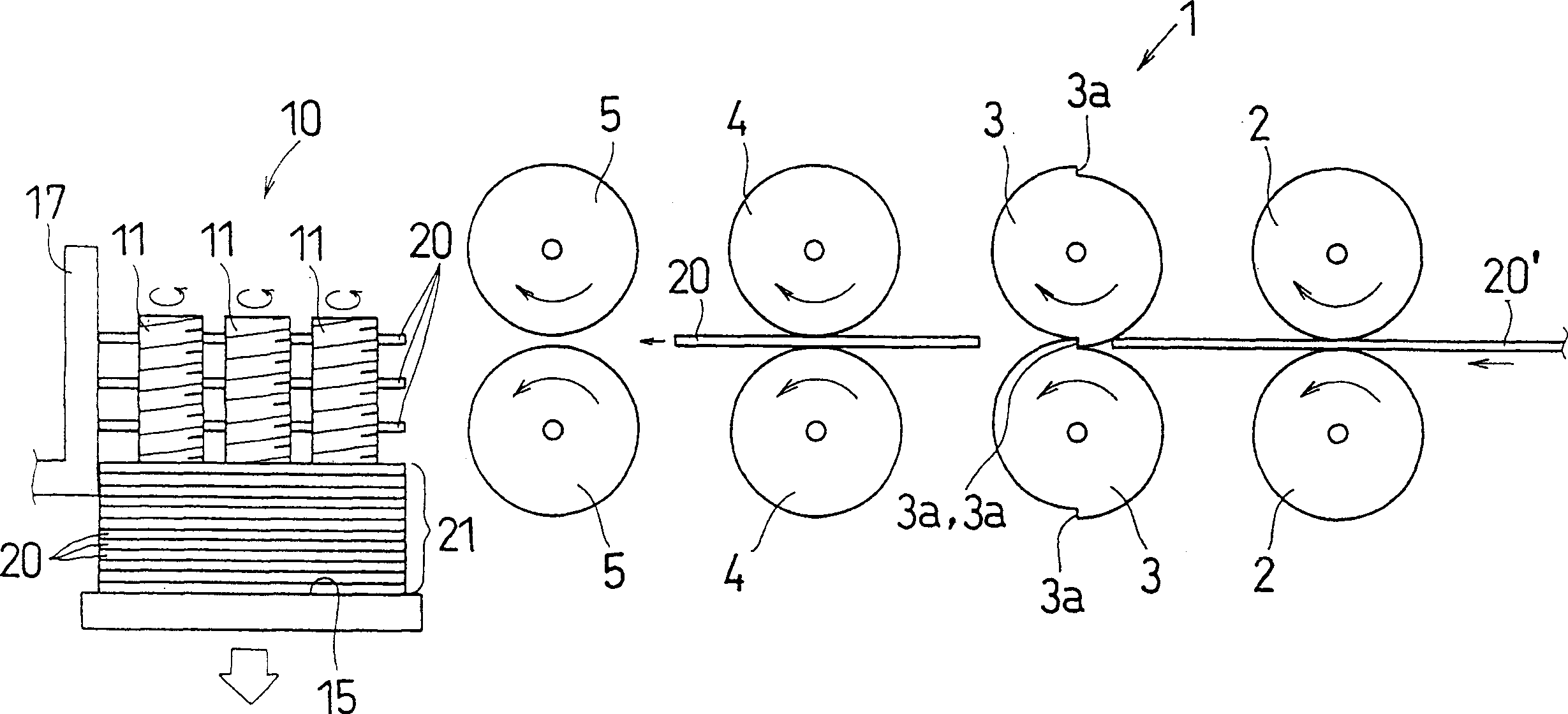
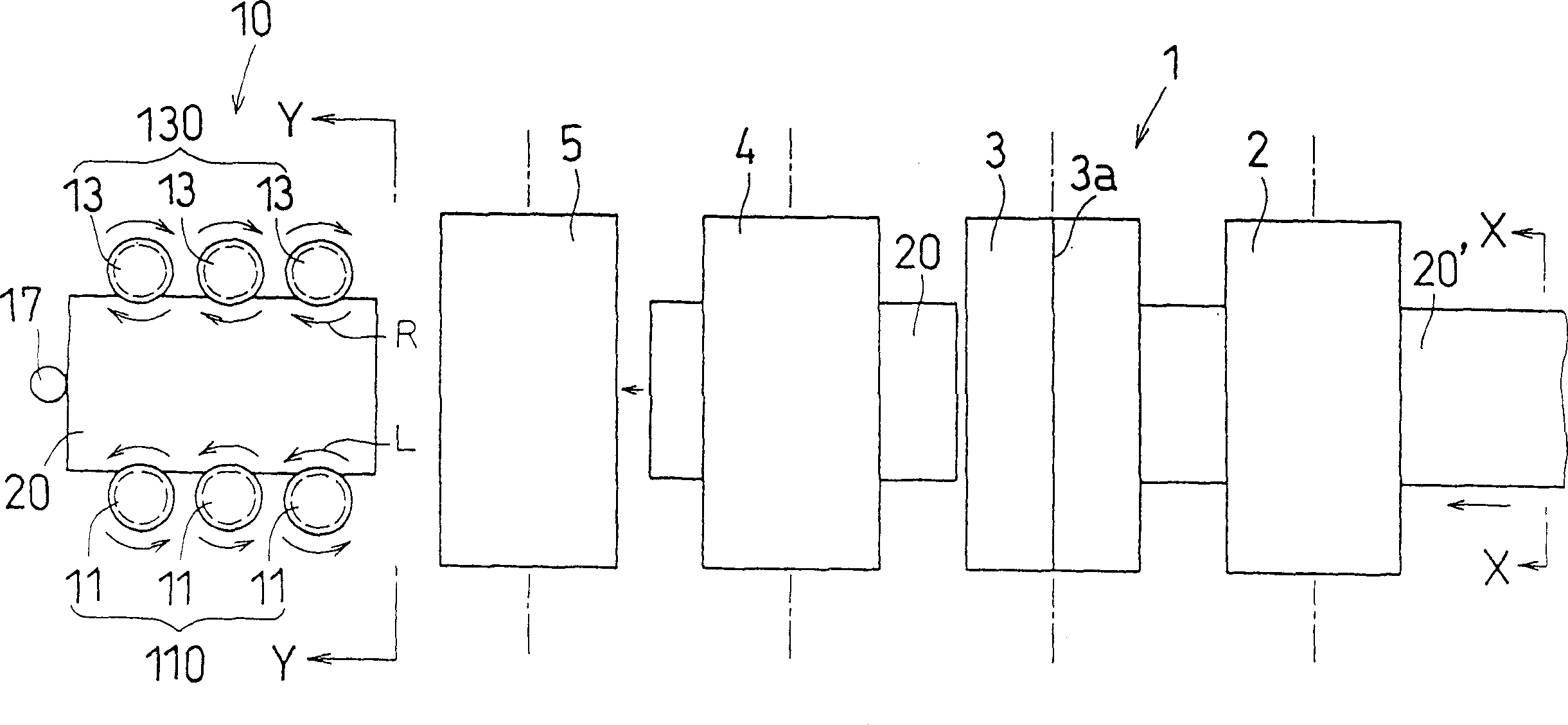
[0045] Figure 1-2 and 3-5 denote a stacker for stacking panels according to an embodiment of the present invention. exist figure 1 and 2 Among them, reference numerals 1 and 10 denote a clipper and a stacker, respectively.

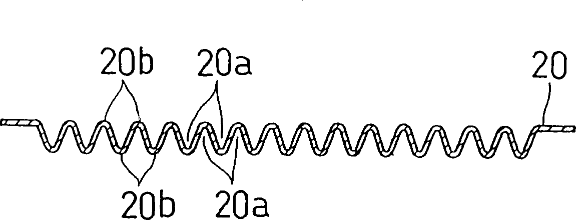
[0046]In this embodiment, the plate 20 to be stacked by the stacker 10 is a metal piece cut by the flying shear 1, or a corrugated inner fin made of aluminum or an aluminum alloy. The inner fin 20 is a member to be provided in a heat exchange tube constituting a heat exchanger such as an evaporator for a vehicle air conditioner. Typically, such inner fins 20 have a length of 150-250 mm and a width of 20-70 mm. Its thickness is particularly small, for example 0.15 mm or less.

[0047] Such as figure 1 and 2 As shown in , the flying shear machine 1 is a kind of long plate member (that is, the inner heat...


PUM


Abstract

A stacker (10) for plate members includes a platform (15) on which plate members (20) are to be stacked and at least one pair of guides (11, 13) disposed at both sides of the platform (15) relative to a transferring direction of the plate members. Each of the guides (11, 13) has a ridge (12a, 14a) spirally formed on a rotational axial portion (12, 14) and a groove (12b, 14b) formed along the ridge (12a, 14a). The aforementioned at least one pair of guides (11, 13) are rotated with opposite edges of the plate member (20) engaged with the grooves (12b, 14b) of the guides (11, 13), to thereby move the plate member (20) toward the platform (15).

Description

[0001] Cross References to Related Applications [0002] This application claims priority to Japanese Patent Application No. 2001-92361, filed March 28, 2001, and U.S. Provisional Application No. 60 / 302,688, filed July 5, 2001, the disclosures of which are incorporated herein by reference Reference. This application claims the benefit of the filing date of US Provisional Application No. 60 / 302,688, filed July 5,2001. technical field [0003] The present invention relates to a stacking machine for panels, a method for stacking panels and stacked panels, and more particularly to a stacking machine preferably for stacking, for example sheared by flying shears. A stacking machine for boards, a method for stacking said boards and stacked boards. Background technique [0004] On the outlet side of the flying shears, a stacker is provided via a transfer device to neatly stack the panels each having a predetermined length and cut by the flying shears. [0005] As such a conventio...

Claims


Application Information

Patent Timeline
Patent Type & Authority Applications(China)
IPC IPC(8): B65G33/06B65G57/03B65G57/11B65H29/42B65H31/10
CPCB65G57/035B65G33/06B65H31/10B65H2701/173B65G57/11B65H29/42
Inventor 塚原昌之桐生守雄
Owner SHOWA DENKO KK
Why Eureka
Try Eureka