Installation for producing a hot-rolled strip

A hot-rolled strip and equipment technology, applied in metal rolling and other directions, can solve the problems of reduced yield, large wet refractory furnace lining, and tundish size limitation, etc.

Inactive Publication Date: 2004-06-02
SIEMENS VAI METALS TECH GMBH
View PDF3 Cites 2 Cited by
  • Summary
  • Abstract
  • Description
  • Claims
  • Application Information

AI Technical Summary

Problems solved by technology

There are restrictions on the size of the tundish due to the need for uniform heating at the start of the tundish operation and the required melt diversion and handling within the tundish
A tundish with a longitudinal extension of more than 10 m is hardly technically feasible in relation to the total throughput of the two twin-roll casters, which would result in very high metal volumes and very large wet refractory linings, and thus Lead to increased consumption of refractory materials and reduced yield

Method used


Image

  • Installation for producing a hot-rolled strip
  • Installation for producing a hot-rolled strip
  • Installation for producing a hot-rolled strip

Examples


Embodiment Construction

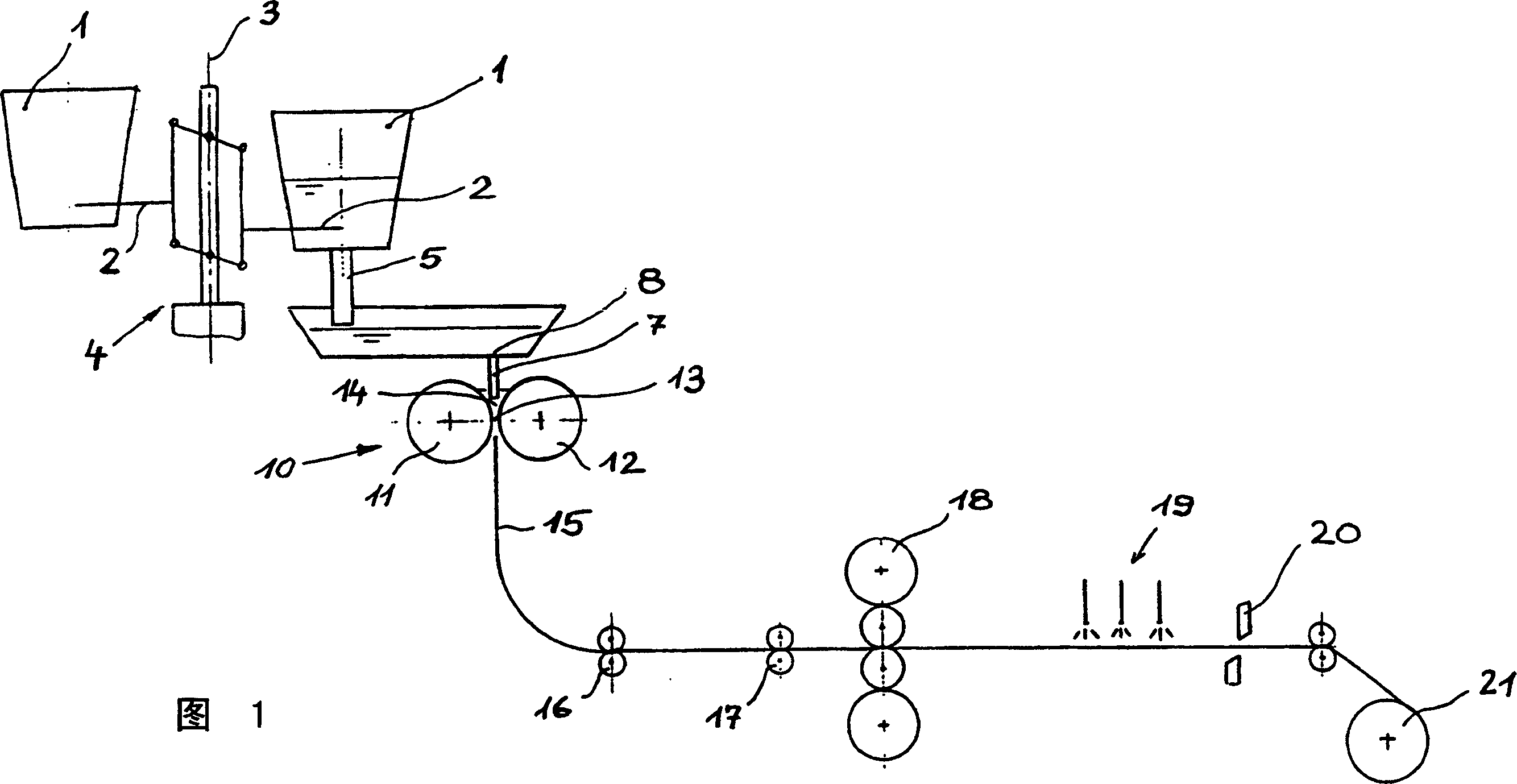
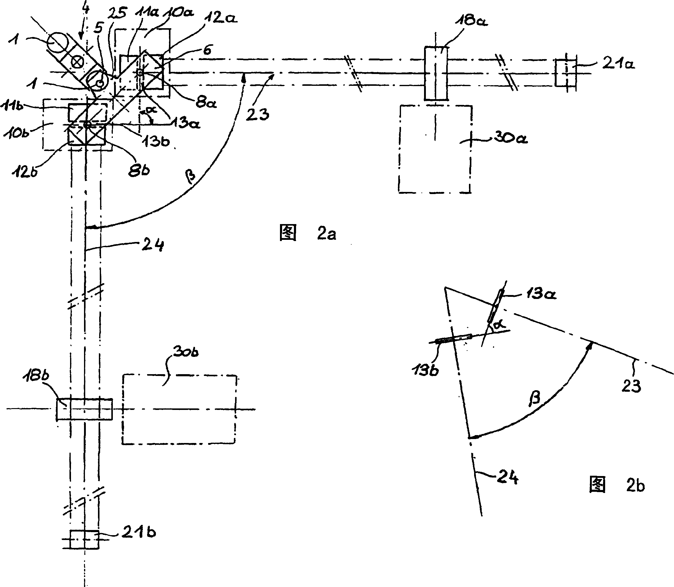
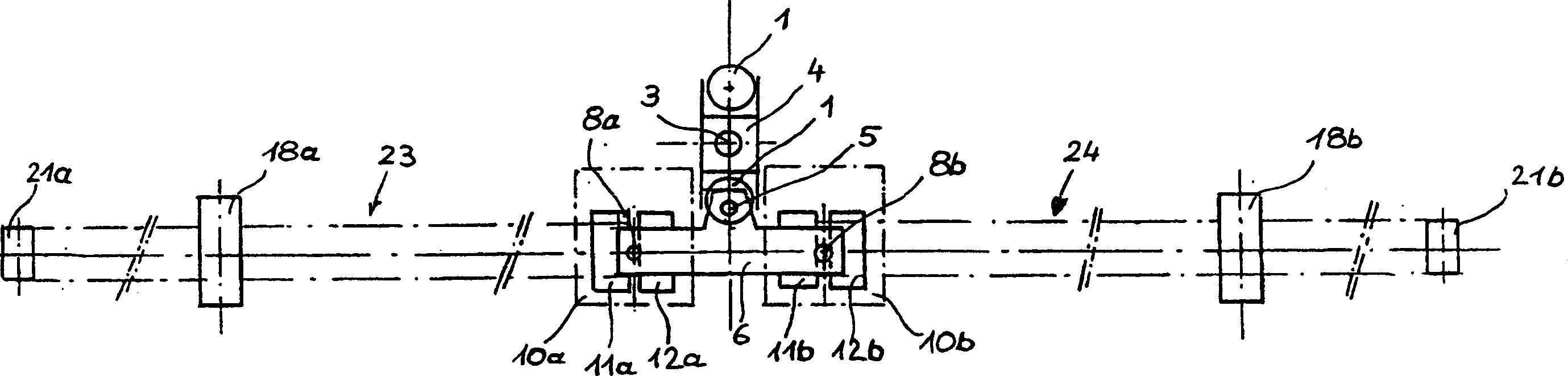
[0025] 1 schematically shows in longitudinal section an overall plant for the production of steel strip from molten steel according to the above-mentioned twin-roll casting method, as is conventional according to the prior art, but limited to the essential parts of the plant. The ladle 1 filled with molten steel is conveyed from the smelting operation to the casting plant by means of a metallurgical trolley or a plant crane (not shown) and from there is inserted into the support 2 of a ladle turret 4 rotating about a vertical axis 3 . From the ladle 1 that has been moved into the casting position, molten steel flows through a melt outlet 5 into a tundish 6 and from there through a bottom outlet 8 formed by a submerged gate 7 to a twin-roll continuous casting device 10 . The twin-roll caster 10 essentially consists of two driven casting rolls 11 , 12 that rotate counter to one another, which are supported via support bearings in a support frame (not shown). The casting rolls 11...


PUM


Abstract

The invention relates to a plant for producing a hot strip from a metal melt in accordance with the twin-roll casting process. To increase the melt throughput in the tundish to above the capacity limit of a one-stranded casting plant operating according to the twin-roll casting process and at the same time to reduce the batch casting times significantly with minimal investment and operating costs, the invention proposes a plant configuration in which a casting ladle (1) with a melt outlet (5) is assigned a tundish (6) for receiving the metal melt from the casting ladle (1), in that this single tundish (6) is equipped with at least two bottom outlets (8a, 8b) for transferring the metal melt to two twin-roll casting devices (10a, 10b), in that each casting nip (13a, 13b) is assigned at least one of the bottom outlets (8a, 8b) of the tundish (6), and the two casting nips (13a, 13b) are arranged at an angle of 15 DEG to 180 DEG , or parallel and offset with respect to one another in terms of their longitudinal extents.

Description

technical field [0001] The invention relates to a plant for producing hot-rolled strip from molten metal according to the twin-roll casting method and using two twin-roll continuous casting installations. Background technique [0002] This plant for the production of hot-rolled thin strip, preferably steel strip, close to the final dimension according to the twin-roll casting method basically consists of two driven casting rolls arranged at a distance from each other and counter-rotating. The axis of rotation lies in a horizontal plane. The casting rolls form a casting roll gap, the lateral boundaries of which are formed by side plates pressed against the ends of the casting rolls. For this purpose, side plates are also known which can be pressed vertically on the ends of the casting rolls. The two casting rollers and the side plates form a melt chamber into which molten metal is fed through a submerged sprue. On the two circumferential surfaces of the cooled casting roll...

Claims


Application Information

Patent Timeline
IPC IPC(8): B21B1/46B22D11/00B22D11/06B22D11/12B22D11/14
CPCB22D11/147B22D11/0622B22D11/06
Inventor G·霍肯比斯勒M·劳特特布
Owner SIEMENS VAI METALS TECH GMBH
Why Eureka
Try Eureka