Method and device for drying ceramic products

A ceramic molding and drying technology, which is applied to electric heating devices, clay products, ceramic molding machines, etc., and can solve problems such as uneven microwave energy

Inactive Publication Date: 2004-06-09
DENSO CORP +1
View PDF0 Cites 22 Cited by
  • Summary
  • Abstract
  • Description
  • Claims
  • Application Information

AI Technical Summary

Problems solved by technology

Specifically, in the case where the ceramic molded products are arranged at irregular intervals in the drying chamber of the drying device, the amount of microwave energy absorbed into the ceramic molded products is not uniform
[0006] Especially in the case of temporary discontinuities in the series of ceramic moldings in the drying chamber, adjacent ceramic moldings may overdry by absorbing increased amounts of microwave energy
In existing drying plants, the ceramic moldings therefore need to be continuously loaded into the drying tunnel without any gaps

Method used


Image

  • Method and device for drying ceramic products
  • Method and device for drying ceramic products
  • Method and device for drying ceramic products

Examples


no. 1 example

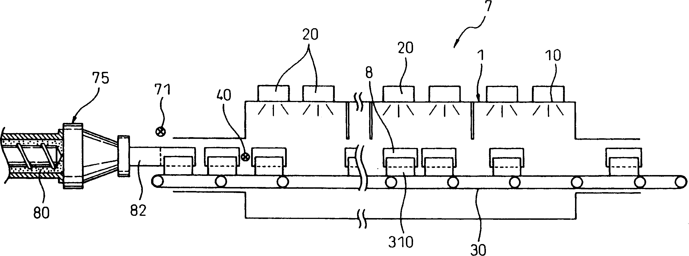
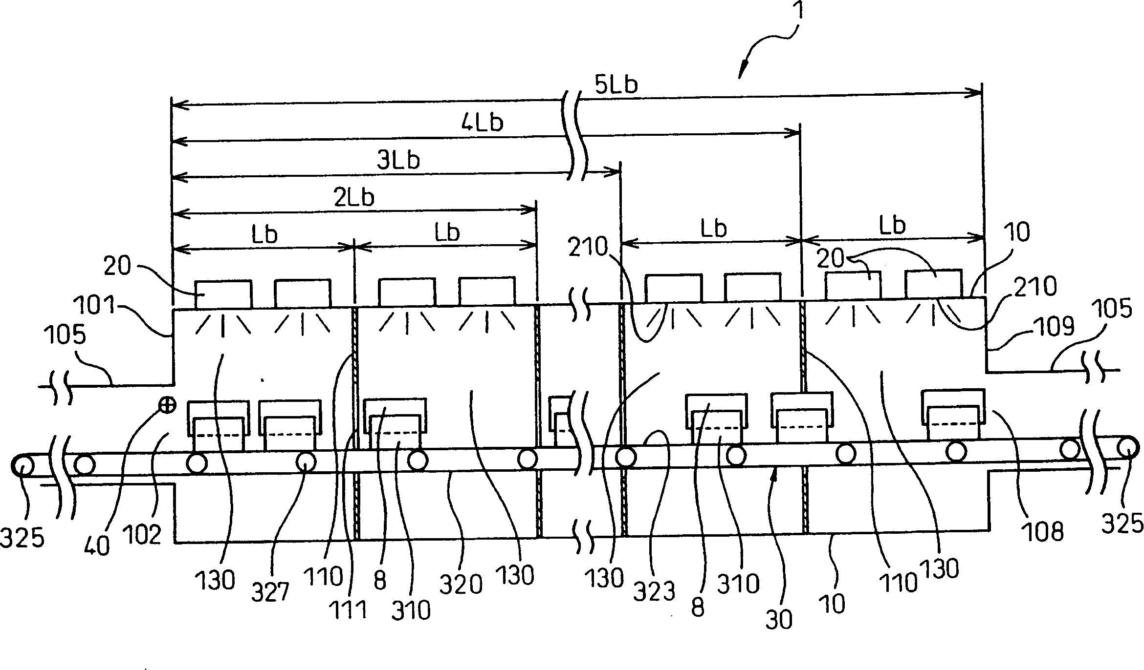
[0039] refer to Figure 1-5 A drying apparatus for ceramic molded articles according to one embodiment of the present invention is explained.

[0040] Such as figure 2 As shown, the drying device 1 according to this embodiment includes a Figure 4 ) drying chamber 10, a plurality of microwave generators 20 for supplying microwave energy in the frequency range of 300MHz to 300GHz to the drying chamber 10, and a conveyor 30 through which ceramic moldings 8 are continuously loaded and conveyed Through and out of the drying chamber 10 .

[0041] A plurality of microwave generators 20 and sensors 40 for detecting distribution of ceramic molded articles 8 in the drying chamber 10 are arranged in the drying chamber 10 along the conveying direction of the conveyor 30 .

[0042] The output of each microwave generator 20 is adapted to vary according to the distribution of the ceramic molded product 8 detected by the sensor 40 .

[0043] The structure of the device will be described...

no. 2 example

[0111] According to this embodiment, a plurality of drying areas adapted to move with the operation of the conveyor are formed instead of the drying sections fixedly arranged in the drying chamber in the first embodiment.

[0112] In this example, if Figure 10 As shown, a plurality of reflectors 345 for reflecting microwave energy are mounted on a part of the support instead of the partition wall of the drying chamber according to the first embodiment. The reflector 345 forms the drying area 340 in the drying chamber 10 . Warm, the ceramic moldings 8 placed on the support are arranged vertically instead of horizontally.

[0113] This embodiment is described in more detail below.

[0114] In the drying device 1 according to this embodiment, a substantially plate-shaped reflector 345 for reflecting microwave energy is mounted on the end of each of at least a part of the supports along the conveying direction and substantially at right angles to the conveying direction. .

...

no. 3 example

[0160] This embodiment relates to a case in which at least one radio wave absorber is arranged on the inner wall of the drying chamber instead of the partition wall that limits the radiation range of microwave energy in the drying device according to the first embodiment.

[0161] In the drying device 1 according to this embodiment, as Figure 13 As shown, a plurality of radio wave absorbers 440 are installed on the inner wall of the drying chamber 10 . The radio wave absorber 440 limits the microwave radiation range of each microwave generator 20 .

[0162]Specifically, in the drying chamber 10 having the radio wave absorber 440 installed on its inner wall, microwaves supplied into the drying chamber 10 rarely reach far points by being repeatedly reflected. Through this drying chamber 10, as Figure 12 As shown, the microwave energy constituting the direct wave generated from the microwave generator can dry the ceramic molding 8 .

[0163] According to this embodiment, the...


PUM

PropertyMeasurementUnit
lengthaaaaaaaaaa

Abstract

An apparatus and a method, for drying ceramic molded articles, are disclosed. A drying apparatus (1) comprises a drying chamber (10) for accommodating ceramic molded articles (8), a plurality of microwave generators (20) for supplying microwave energy into the drying chamber, and a conveyor (30) for charging the ceramic molded articles (8) continuously into the drying chamber (10), conveying the ceramic molded articles through the drying chamber, and delivering the ceramic molded articles from the drying chamber. The drying chamber (10) has arranged therein a plurality of the microwave generators (20) and at least a sensor (40) for detecting the distribution of the ceramic molded articles (8) in the drying chamber (10). Each microwave generator (20) is adapted to change the output thereof in accordance with the distribution of the ceramic molded articles (8) detected by the sensor (40).

Description

technical field [0001] The present invention relates to a method and apparatus for drying ceramic objects molded by extrusion. Background technique [0002] In the manufacture of ceramic moldings, clay-like ceramic materials are extruded, dried and baked. [0003] An existing device for drying ceramic moldings is disclosed in, for example, JPP (Japanese Unexamined Patent Publication) 2000-44326, wherein a part of the channel for conveying extruded ceramic moldings is covered by a drying chamber, conveyed through The ceramic moldings of the drying chamber are dried by means of radiated microwave energy. [0004] In existing drying devices, microwave energy needs to be irradiated slowly and uniformly in order to dry ceramic moldings uniformly without any deformation. For this purpose, a drying process is usually carried out in which a plurality of ceramic moldings are loaded and conveyed longitudinally along the conveying direction in a drying tunnel in order to radiate micr...

Claims


Application Information

Patent Timeline
Patent Type & Authority Applications(China)
IPC IPC(8): C04B33/30B28B3/20B28B11/00B28B11/24C04B35/64F26B3/347F26B15/12F26B25/00H05B6/78
CPCB28B3/206B28B2003/203H05B2206/046B28B11/243C04B2235/94F26B15/12H05B6/78F26B25/003C04B2235/6021C04B35/62655F26B3/347B28B11/241
Inventor 石川谕史加藤广己后藤章一美浓部富男
Owner DENSO CORP
Why Eureka
Try Eureka