Clamping profile material

A profile and clamping technology, which is applied in the direction of building types, friction-clamped detachable fasteners, tents/canopies, etc., can solve security problems, losses, etc., to eliminate sealing problems and increase possibilities Effect

Inactive Publication Date: 2004-06-09
迪特尔·林克
View PDF3 Cites 3 Cited by
  • Summary
  • Abstract
  • Description
  • Claims
  • Application Information

AI Technical Summary

Problems solved by technology

Although it has been contemplated that the building's membrane would be protected from hail or storms, it has been shown in recent years that extreme weather conditio

Method used


Image

  • Clamping profile material
  • Clamping profile material
  • Clamping profile material

Examples


Embodiment Construction

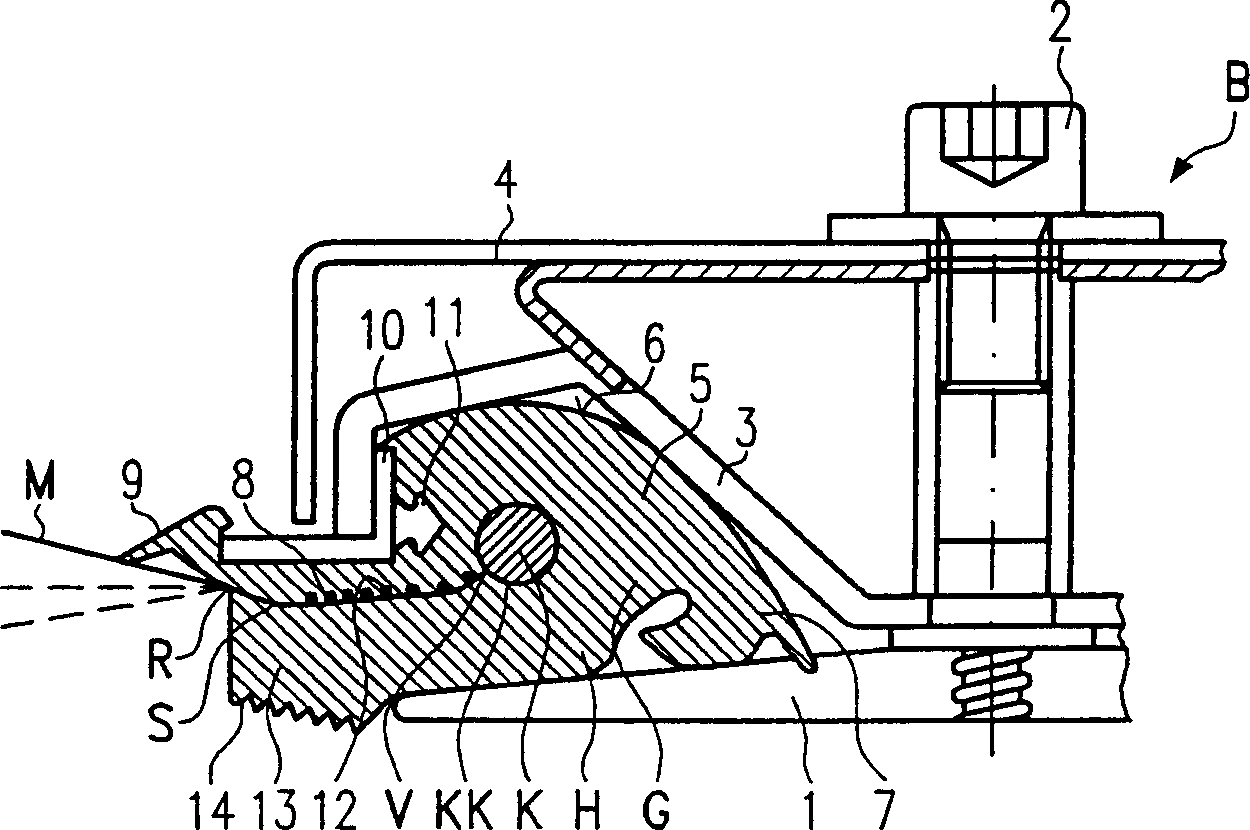
[0028] figure 1 A support 1 of a carrier structure T (not shown in detail) of a membrane construction B is shown. The support structure T is used to fix at least one membrane M (in the form of a plastic film or fabric). Membrane M has at least a single layer, or has (indicated by dotted lines) two layers, or even three layers. The edge R of the membrane M is secured by means of the weatherstrip K in the weatherstrip channel KK of the holding profile H, so that the edge R extends through the slot outlet S of the holding profile H to the outside. For example, the wing gap outlet S starts at the throat portion V close to the weatherstrip channel KK. At least that part of the holding profile H in the region of the weatherstrip channel KK or the airfoil outlet S consists of rubber or elastomer G, for example of vulcanized EPDM or silicone rubber or the like. Preferably the entire clamping profile H consists of such a material. The consistency of the holding profile H is soft an...


PUM


Abstract

A membrane roof or temporary building construction facade has a large plastic or textile panel (M) which is supported and secured at its edges (R) by a profile anchorage clamp fitting (H). The membrane (M) terminates at its periphery in an anchorage beading profile (K) which locates within a matching groove (KK) forming part of the clamping profile (5). The clamping profile is located and clamped (2) within a surrounding metal profile (B).

Description

technical field [0001] The invention relates to a clamping profile according to the preamble of claim 1 and to a membrane construction according to the preamble of claim 15 . Background technique [0002] In recent years, a new construction technique has been disclosed, eg for swimming pools, arcade courtyards, gas stations or veneers, known in architecture as membrane construction. Such constructions, in the form of roof coverings or veneers, include support rails mounted on the load-bearing structure according to a predetermined grid. The membrane spans are placed on the field between the support rails and their edges are fixed in the support rails. Membranes can be monolayer or multilayer structures and can consist of plastic films or fabrics. The upper and lower sides of the membrane are stretched or covered respectively by means of beams or rope assemblies, or can be inflated by increased internal pressure into so-called air cushions with or without tensioning element...

Claims


Application Information

Patent Timeline
IPC IPC(8): E04H15/20E04H15/64
CPCE04H15/20E04H15/644E04H2015/203E04H15/648E04H15/646
Inventor 休伯特·瑞特于尔根·奥伯迈尔德克·特默迪特尔·林克
Owner 迪特尔·林克
Why Eureka
Try Eureka