Magnetic resonance spectroscopy

A technology of magnetic resonance and magnetic resonance signals, applied in magnetic resonance measurement, material analysis through resonance, measurement devices, etc., can solve problems such as not very strong signals, submersion, and weak FID signal amplitudes

Inactive Publication Date: 2004-06-09
SIEMENS MEDICAL SOLUTIONS USA INC
View PDF0 Cites 5 Cited by
  • Summary
  • Abstract
  • Description
  • Claims
  • Application Information

AI Technical Summary

Problems solved by technology

[0004] In general, the magnitude of the FID signal is weak
When using a single measuring coil, the signal detected by that coil may not be very strong and may be swamped by noise

Method used


Image

  • Magnetic resonance spectroscopy
  • Magnetic resonance spectroscopy
  • Magnetic resonance spectroscopy

Examples


Embodiment Construction

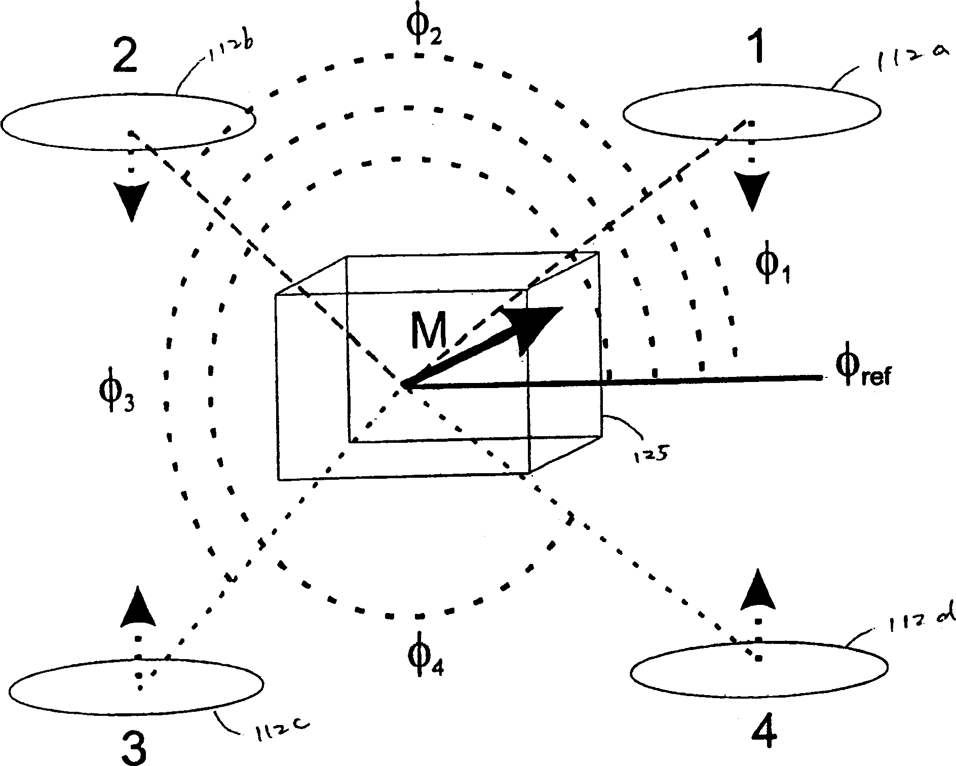
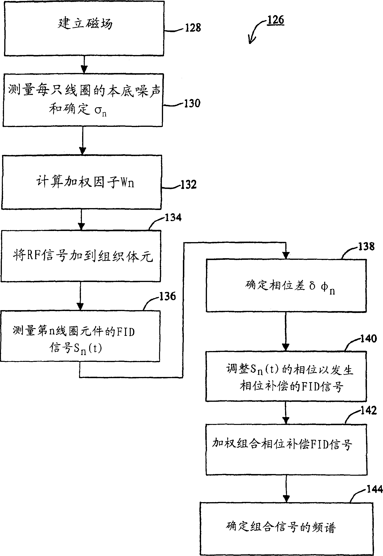
[0024] The magnetic resonance assay system as described matches the phases of FID signals measured by different coil elements of a phased array coil, combines the phase-matched signals in the time domain, and then calculates the spectrum of the combined signal to produce an enhanced Magnetic resonance spectroscopy signal, which reduces the calculation of the Fourier transform.

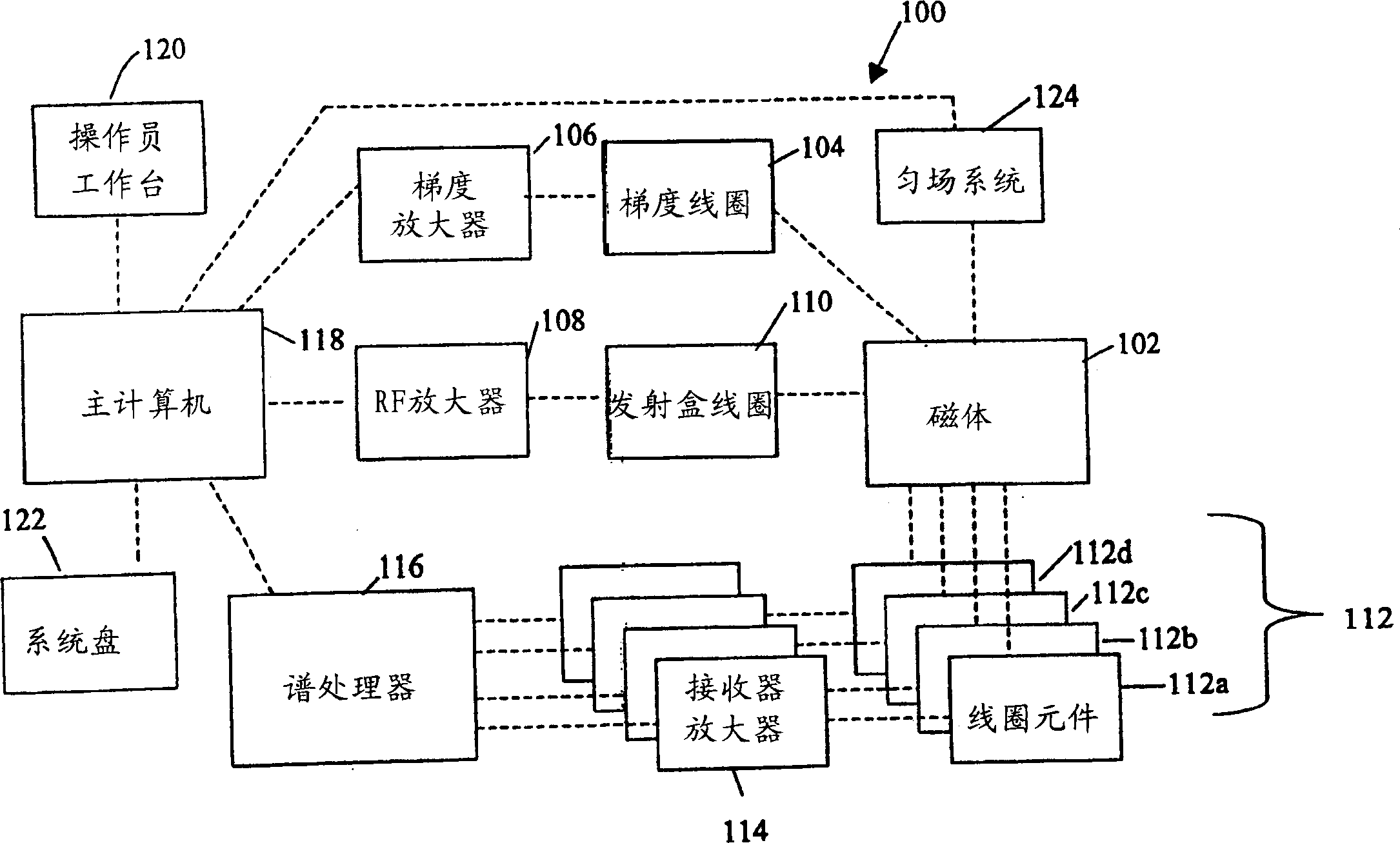
[0025] refer to figure 1 , the magnetic resonance assay system 100 includes a substantially uniform main magnetic field that occurs through an examination region where the patient's body is located. The magnet 102 may be an electromagnet made of superconducting wire. Shimming system 124 corrects for small spatial inhomogeneities in the main magnetic field of the patient's body part under examination. Gradient coils 104 generate linear magnetic field gradients within the main magnetic field at the body part within the examination region. The gradient amplifier 106 generates a current which flows thro...


PUM


Abstract

Magnetic resonance signals that are measured by phase-array coils are combined in the time domain. The phase of the signal measured at each coil is adjusted in the time domain prior to combination with the signals measured at other coils so that the phase of the signals are substantially equal to one another. The combined time domain signal is then converted into a frequency domain signal for spectroscopic analysis.

Description

[0001] This application claims priority to US Provisional Patent Application No. 60 / 427,641, filed 11 / 19 / 2002, entitled "Magnetic Resonance Assays," the contents of which are hereby incorporated by reference as if fully set forth. technical field [0002] The present invention relates to magnetic resonance assays. Background technique [0003] Magnetic resonance assays use the phenomenon of magnetic resonance to study the physical, chemical and biological properties of substances. The object to be inspected is placed in a magnetic field, and then a pulsed radio frequency signal (RF) is aimed at a voxel in the object to induce magnetic resonance. The magnetic resonance signals can be detected with measuring coils in the vicinity of the voxel. The magnetic resonance signal resembles a sine wave, and its frequency ω decays with a time constant, which is called a free induction decay signal (FID). Different types of atoms in the volume will induce different magnetic resonance ...

Claims


Application Information

Patent Timeline
Patent Type & Authority Applications(China)
IPC IPC(8): G01R33/34G01N24/00G01R33/32G01R33/3415G01R33/465
CPCG01R33/3415
Inventor M·A·布朗
Owner SIEMENS MEDICAL SOLUTIONS USA INC
Why Eureka
Try Eureka