Method and circuit reducing reverse currents in synchronous rectifier converter circuit

A technology of synchronous rectifier and reverse current, which is applied to conversion equipment with intermediate conversion to AC, conversion of DC power input to DC power output, instruments, etc., which can solve the problems of increasing system complexity and cost, and achieve a small number of components , the effect of less complexity

Inactive Publication Date: 2004-06-09
TELEFON AB LM ERICSSON (PUBL)
View PDF0 Cites 20 Cited by
  • Summary
  • Abstract
  • Description
  • Claims
  • Application Information

AI Technical Summary

Problems solved by technology

However, this method requires the use of a load current sense circuit, which increases system complexity and cost, and requires disconnection of the synchronous rectification circuit for a period of time

Method used


Image

  • Method and circuit reducing reverse currents in synchronous rectifier converter circuit
  • Method and circuit reducing reverse currents in synchronous rectifier converter circuit
  • Method and circuit reducing reverse currents in synchronous rectifier converter circuit

Examples


Embodiment Construction

[0025] Detailed description of the preferred embodiment

[0026] The following is a detailed description of the present invention. Prior art circuits are first discussed, followed by a description of several preferred embodiments and alternatives of the present invention and a discussion of advantages.

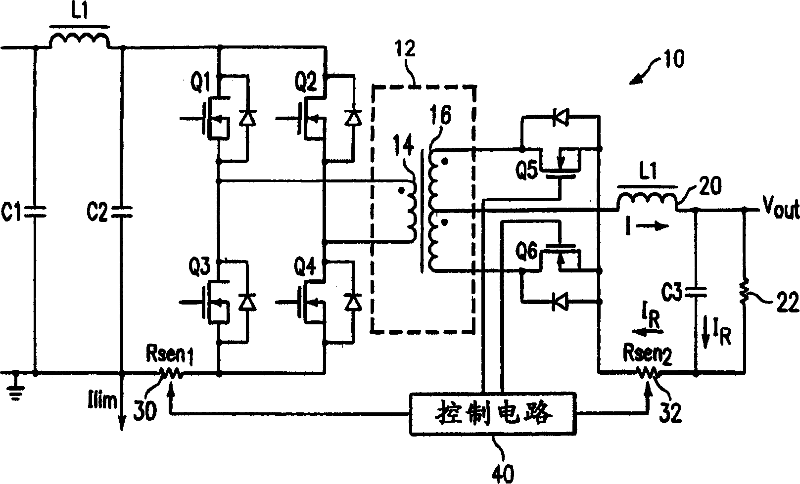
[0027] FIG. 1 shows a prior art externally driven full-bridge synchronous rectification converter circuit, generally designated 10 . Specifically, synchronous rectification circuit 10 includes a primary side synchronous rectification circuit comprising four synchronous rectifiers Q1, Q2, Q3 and Q4 operably coupled to primary winding 14 of transformer 12 as shown. Primary winding 14 of transformer 12 is inductively coupled to secondary winding 16 to perform a DC-to-DC conversion function as is well known in the art. In operation, a signal from primary winding 14 of transformer 12 is induced onto secondary winding 16 which is center tapped to drive output inductor 20 as shown....


PUM


Abstract

A converter with synchronous rectification is driven in such a way so that the reverse currents do not build up and cause damage or limit the efficiency of the circuit. Negative currents are self-adjusted to very small percent of load current, so the converter will not have problem when in parallel with other modules. An auxiliary winding is used to allow an output inductor to drive the secondary side rectifiers thereby limiting their conduction time as reverse currents increase. The primary side conduction timer are extended by operation of their anti-diodes so that reverse currents are limited naturally without the use of dedicated load sensing and shutdown circuits.

Description

technical field [0001] This invention relates generally to distributed power systems and their applications, and more particularly to synchronous rectification converters that limit the increase in reverse current by automatically adjusting to a very small percentage of the load current, so paralleling the converter with other modules is not a problem . Background of the invention [0002] As logic integrated circuits have moved to lower operating voltages in search of higher operating frequencies, and as overall system sizes continue to shrink, power supply designs with smaller and more efficient power modules are required. In an effort to improve efficiency and increase power density, synchronous rectification has become a necessity for such applications. Synchronous rectification has gained widespread popularity over the past decade as low-voltage semiconductor devices have evolved to make synchronous rectification a viable technology. [0003] At the same time, distrib...

Claims


Application Information

Patent Timeline
Patent Type & Authority Applications(China)
IPC IPC(8): H02M3/28H02M3/335
CPCY02B70/1475H02M3/33592Y02B70/10
Inventor M·N·孙
Owner TELEFON AB LM ERICSSON (PUBL)
Why Eureka
Try Eureka