Motor driven resistance spot welding gun

A technology of motor drive and welding torch, which is applied in the direction of resistance welding equipment, resistance electrode base, electromechanical device, etc. It can solve the problems of damage, etc., and achieve the effect of simple structure, equipment reduction and equipment cost reduction

Inactive Publication Date: 2004-06-30
HONDA MOTOR CO LTD
View PDF1 Cites 20 Cited by
  • Summary
  • Abstract
  • Description
  • Claims
  • Application Information

AI Technical Summary

Problems solved by technology

As a result, the rotors and the feed screw, which rest against each other at the junction, slip and tend to be damaged

Method used


Image

  • Motor driven resistance spot welding gun
  • Motor driven resistance spot welding gun
  • Motor driven resistance spot welding gun

Examples


Embodiment Construction

[0044] Best Mode for Carrying Out the Invention

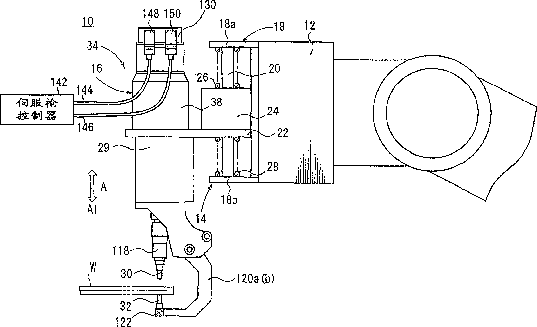
[0045] figure 1 Shown is a side view, partly omitted from illustration, of a motor-driven welding gun fastening device according to a first embodiment of the invention, the welding gun being mounted at the distal end of the robot arm 12 . The motor-driven welding torch 10 is configured as a C-shaped welding torch having a movable electrode tip 30 that can move linearly toward or away from a fixed electrode tip 32 . However, the motor-driven welding torch 10 is not limited to such a C-shaped welding torch, but may be provided as an X-shaped welding torch having a movable electrode tip that can swing relative to a fixed electrode tip.

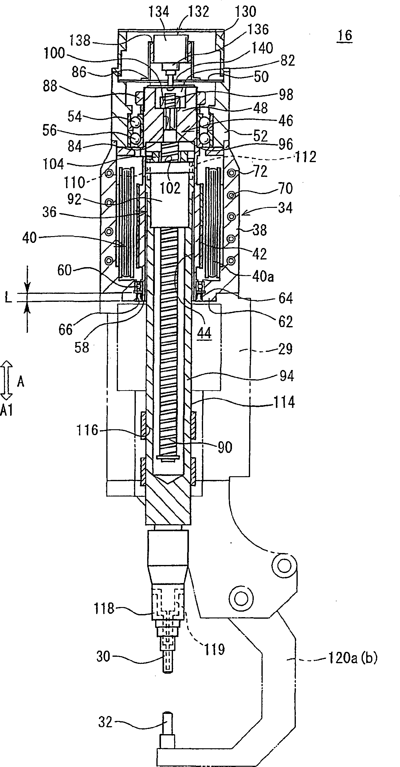
[0046] The motor driven welding gun 10 includes a welding gun bracket 14 and a welding gun assembly 16 . A welding torch bracket 14 is mounted on the distal end of the robot arm 12 and supports a welding torch assembly 16 . The torch holder 14 has a torch holder frame 18 with an upper panel 18a...


PUM


Abstract

A motor-driven welding gun has a servomotor (34) for displacing a movable electrode tip (30) toward and away from a fixed electrode (32). The servomotor (34) has a motor housing (38) with a copper pipe (72) which is inserted therein when the motor housing (38) is cast. The copper pipe (72) provides a coolant passage (70) in the motor housing (38) for supplying a coolant therethrough. When the coolant passage (70) is supplied with the coolant, the motor housing (38) is forcibly cooled, reducing the amount of heat generated by the servomotor (34).

Description

technical field [0001] The present invention relates to a motor-driven welding torch having a pair of electrode tips and a feed screw connected to a servo motor for driving one electrode tip toward or away from the other electrode tip. technical background [0002] Spot welding guns are used for welding, e.g. welding overlapping metal sheets. Typically, such spot welding guns include air-operated or motor-driven servo guns that simplify control of the opening between a pair of electrode tips. [0003] Generally, a motor-driven welding gun as a motor-driven servo welding gun includes: a servo motor; a pair of electrode tips; a feed screw device connected with the servo motor for driving one of the electrode tips to move relative to the other electrode tip . The workpieces, which are to be welded to each other, are clamped between the electrode tips. While the electrode tip is pressurized by the electrode tip operated by the servo motor, current flows through the workpieces...

Claims


Application Information

Patent Timeline
Patent Type & Authority Applications(China)
IPC IPC(8): B23K11/31H02K7/06
CPCH02K7/06B23K11/317B23K11/315
Inventor 美和浩中林繁光佐佐木仁志庄司正明桥本裕树栗原治钉宫卓郎清水明义吉见重则
Owner HONDA MOTOR CO LTD
Why Eureka
Try Eureka