Permanent magnet rings

A permanent magnet and magnet technology, applied in the direction of permanent magnets, magnetic fields generated by permanent magnets, permanent magnet manufacturing, etc., can solve the problem of less effect, achieve strong magnetic attraction, promote blood circulation, and good wearability

Inactive Publication Date: 2004-07-07
SAGAMI CHEM METAL
View PDF0 Cites 2 Cited by
  • Summary
  • Abstract
  • Description
  • Claims
  • Application Information

AI Technical Summary

Problems solved by technology

Therefore, in the case of existing health care appliances or health decorations using magnetism, the effect of the magnetic field lines generated by the permanent magnets on the various parts of the body becomes less and becomes a prominent problem.

Method used


Image

  • Permanent magnet rings
  • Permanent magnet rings
  • Permanent magnet rings

Examples


Embodiment Construction

[0062] Next, preferred embodiments of the present invention will be described with reference to the drawings.

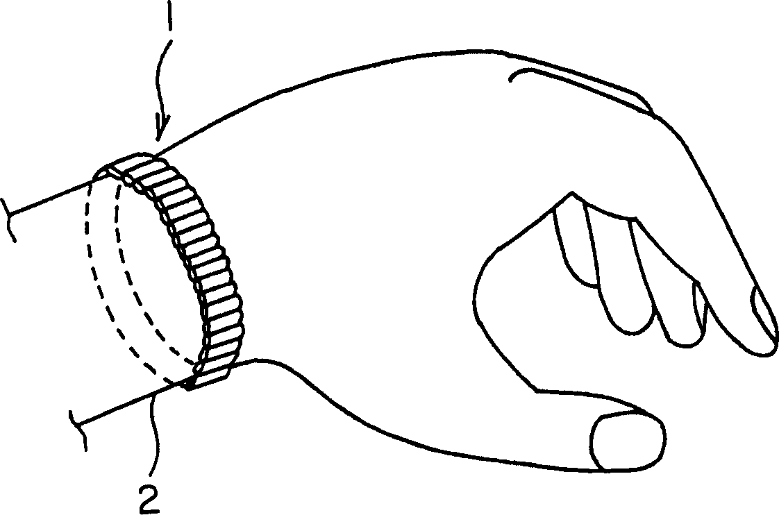
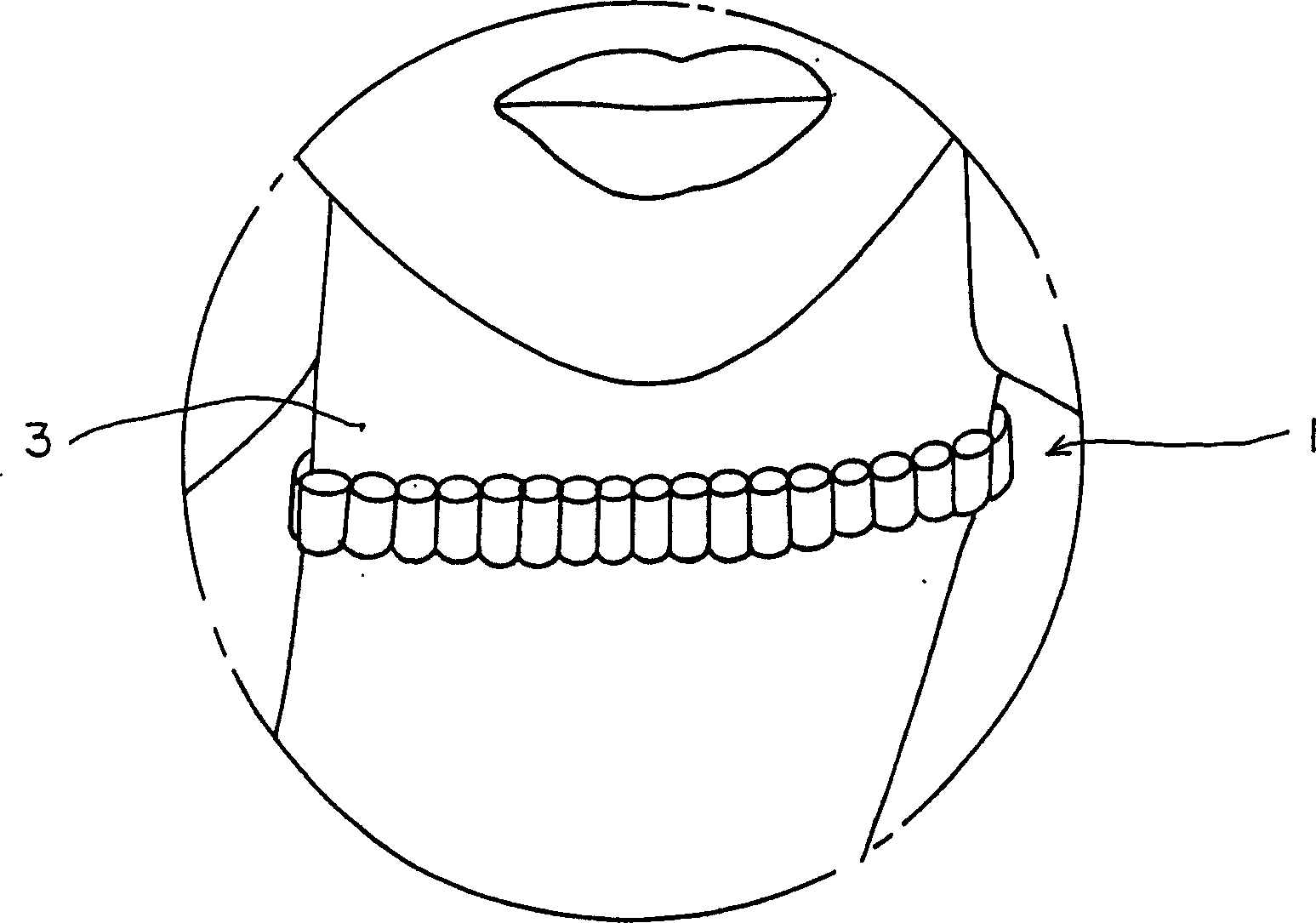
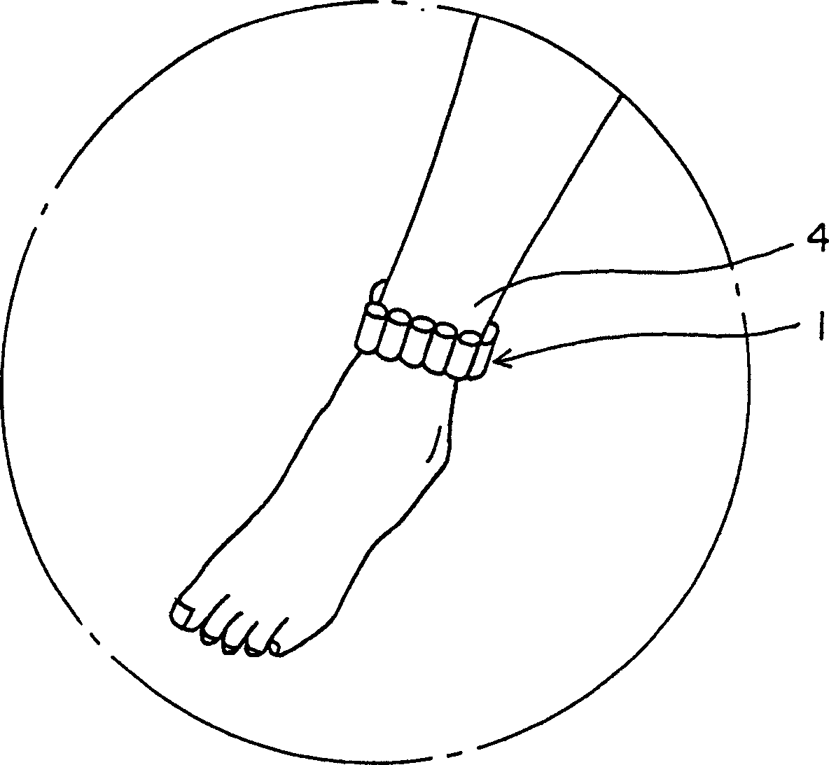
[0063] The permanent magnet ring 1 of the present invention, or as figure 1 worn on the user's wrist 2 for use as shown, or as figure 2 Worn around the neck 3 use as shown, or as image 3 Shown is worn around the ankle 4 uses. Others not shown can be used as rings, bracelets or anklets.

[0064] The permanent magnet ring 1 is to be as Figure 4 The shown unit permanent magnets 5a, 5b, 5c... are as Figure 5 The shown pluralities 5a, 5b, 5c, 5d... are formed by being connected to each other by magnetic attraction. exist Figure 4 , 5 In the embodiment of , 6, an example is shown in which each of the unit permanent magnets 5 a , 5 b , 5 c , 5 d . Therefore, it is easy to connect a predetermined number of the plural columnar unit permanent magnets 5a, 5b, 5c, 5d, . In this case, if the two end faces of each column of the cylindrical unit magnets 5a, 5b, 5c, 5d...


PUM


Abstract

In a permanent magnet ring (1) formed by arranging a plurality of unit permanent magnets (21a, 21b, 21c . . . ), each of a plurality of the unit permanent magnets (21a, 21b, 21c . . . ) is formed in a circular cylindrical shape having a circular cross section, and a predetermined number of the unit permanent magnets are magnetically attracted each other so as to form a ring shape having a predetermined size, so that it is possible for the user to easily structure the permanent magnet ring (1) having a desired size, and it is possible to attach as many the unit permanent magnets as possible so as to be able to apply proper magnetic force lines to each part of the body.

Description

technical field [0001] The present invention relates to a permanent magnet ring, and more specifically, to a permanent magnet that is worn around the wrist, ankle, neck, arm, leg, etc. of the body, and uses the magnetic effect output from the permanent magnet ring to promote blood circulation, etc. Ring improvements. Background technique [0002] It is well known to use permanent magnets to form rings and wear them around the wrists, ankles, necks, etc. of the body, as necklaces or bracelets, etc., which are expected to utilize the magnetic effect output from the permanent magnet rings to promote blood circulation, etc. As a product, many permanent magnet rings have been used in practice and are also being proposed as solutions. [0003] One of the existing examples is Japanese Utility Model Registration No. 3033643. That is, a health care appliance that utilizes magnetism. The health care appliance that utilizes magnetism is composed of a curved, elastic ring with opposit...

Claims


Application Information

Patent Timeline
Patent Type & Authority Applications(China)
IPC IPC(8): H01F7/02A61N2/06A61N2/08H01F41/02
CPCA44D2203/00H01F41/0273A61N2/06H01F41/026Y10T428/29Y10T428/325Y10T428/32Y10T428/2991H01F7/02Y10S63/90
Inventor 福田重男
Owner SAGAMI CHEM METAL
Why Eureka
Try Eureka