Check patentability & draft patents in minutes with Patsnap Eureka AI!

Overcurrent detection and protection apparatus for switching element

A switching element and overcurrent technology, applied in the direction of overcurrent protection, automatic disconnection emergency protection device, electrical components, etc., can solve the problems of overheating and damage of semiconductor switch wires

Inactive Publication Date: 2004-07-07
YAZAKI CORP
View PDF0 Cites 28 Cited by
  • Summary
  • Abstract
  • Description
  • Claims
  • Application Information

AI Technical Summary

Problems solved by technology

This overcurrent can overheat and damage the semiconductor switches provided for the load and the wires connecting the load to the battery

Method used


Image

  • Overcurrent detection and protection apparatus for switching element
  • Overcurrent detection and protection apparatus for switching element
  • Overcurrent detection and protection apparatus for switching element

Examples


no. 2 approach

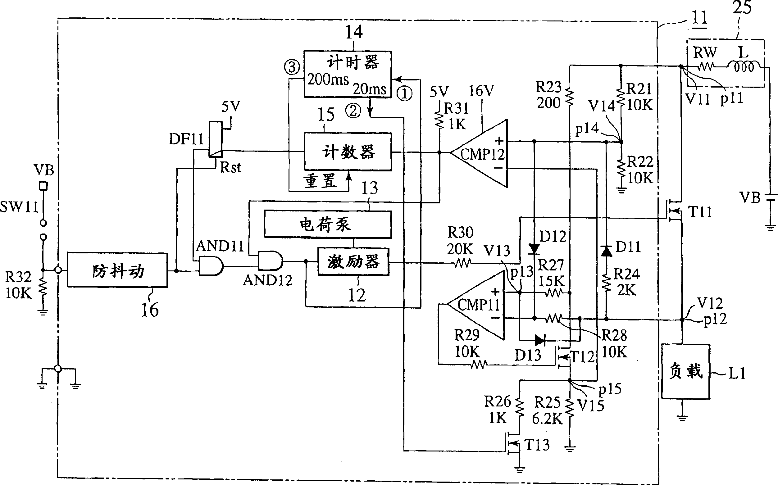
[0139] FIG. 5 is a circuit diagram showing an overcurrent detection / protection device 21 and its peripheral devices according to a second embodiment of the present invention. In addition to the structure of the first embodiment, the second embodiment employs an inverter circuit NOT11, an AND circuit AND13, and an OR circuit OR11. The other parts of the second embodiment and figure 1 The same as the first embodiment.

[0140] In FIG. 5, if the output of the comparator CMP12 is low and if the first timer of the timer 14 is running, the latch DF11 is closed to force the switching element T11 to be turned off. If the output of the comparator CMP12 is low and if the first timer is operating, the circuit between the power supply VB and the load L1 is passing an overcurrent due to a dead short. Therefore, switching element T11 is turned off immediately to protect the circuit and counter 15 is not required to count to four. Compared with the first embodiment, the second embodiment ...


PUM


Abstract

An overcurrent detection / protection apparatus protects a switching element (T11) from an overcurrent. When a current flows through the switching element, a voltage drop occurs. The apparatus amplifies the voltage drop and generates a first voltage (V15). And, the apparatus divides a voltage at a node between the switching element and a load and generates a second voltage (V14). If the first voltage exceeds the second voltage, the apparatus concludes that there is an overcurrent. Due to wiring inductance (L) and the ON resistance (Ron) of the switching element, the second voltage decreases when an overcurrent flows. Accordingly, the apparatus can instantaneously detect an overcurrent, which may be caused by a dead short, and rendering the switching element inoperative, to thereby protect the switching element and wiring between the switching element and the power source. The apparatus employs no shunt resistors, and therefore, is compact and low-cost.

Description

technical field [0001] The invention relates to an overcurrent detection device for detecting an overcurrent flowing through a semiconductor switch and a line arranged between a load and a power supply. Background technique [0002] A load such as a light bulb or a motor installed in eg a car receives an operating DC voltage from the battery. Such loads are sometimes subject to overcurrent caused by circuit damage or malfunction. This overcurrent can overheat and damage the semiconductor switches provided for the load as well as the wires connecting the load to the battery. [0003] In order to quickly detect an overcurrent and cut off a circuit between a power source and a load, various overcurrent detection and disconnection circuits have been proposed. An example of a prior art overcurrent detection circuit involves arranging a shunt resistor in a line between a power supply and a load, detecting a terminal voltage of the shunt resistor, and switching the load to a volt...

Claims


Application Information

Patent Timeline
Patent Type & Authority Applications(China)
IPC IPC(8): G01R19/165H02H3/08H02H3/087H02H7/00H02H7/20H03K17/06H03K17/08H03K17/082H03K17/687
CPCH03K17/063H03K17/0822H02H3/087H03K17/082
Inventor 大岛俊藏
Owner YAZAKI CORP
Features
  • R&D
  • Intellectual Property
  • Life Sciences
  • Materials
  • Tech Scout
  • Unparalleled Data Quality
  • Higher Quality Content
  • 60% Fewer Hallucinations
Learn More