Working position measurer

A measuring device and operation technology, which can be used in measuring devices, active optical measuring devices, measuring instruments, etc., and can solve the problems of complex structure and high price.

Active Publication Date: 2004-07-14
KK TOPCON
View PDF0 Cites 27 Cited by
  • Summary
  • Abstract
  • Description
  • Claims
  • Application Information

AI Technical Summary

Problems solved by technology

[0021] However, since the relatively long light-receiving part 23 is formed by arranging a plurality of relatively short light-receiving elements 25, there is a problem of high cost.
And, make above-mentioned light-receiving part 23 produce the device that lifts and moves usefulness, its driving part, and the control part etc. that this driving part is used all need to have complicated structural form, so this device is also a kind of expensive device.

Method used


Image

  • Working position measurer
  • Working position measurer
  • Working position measurer

Examples


Embodiment Construction

[0043] Embodiments of the present invention are described below with reference to the drawings.

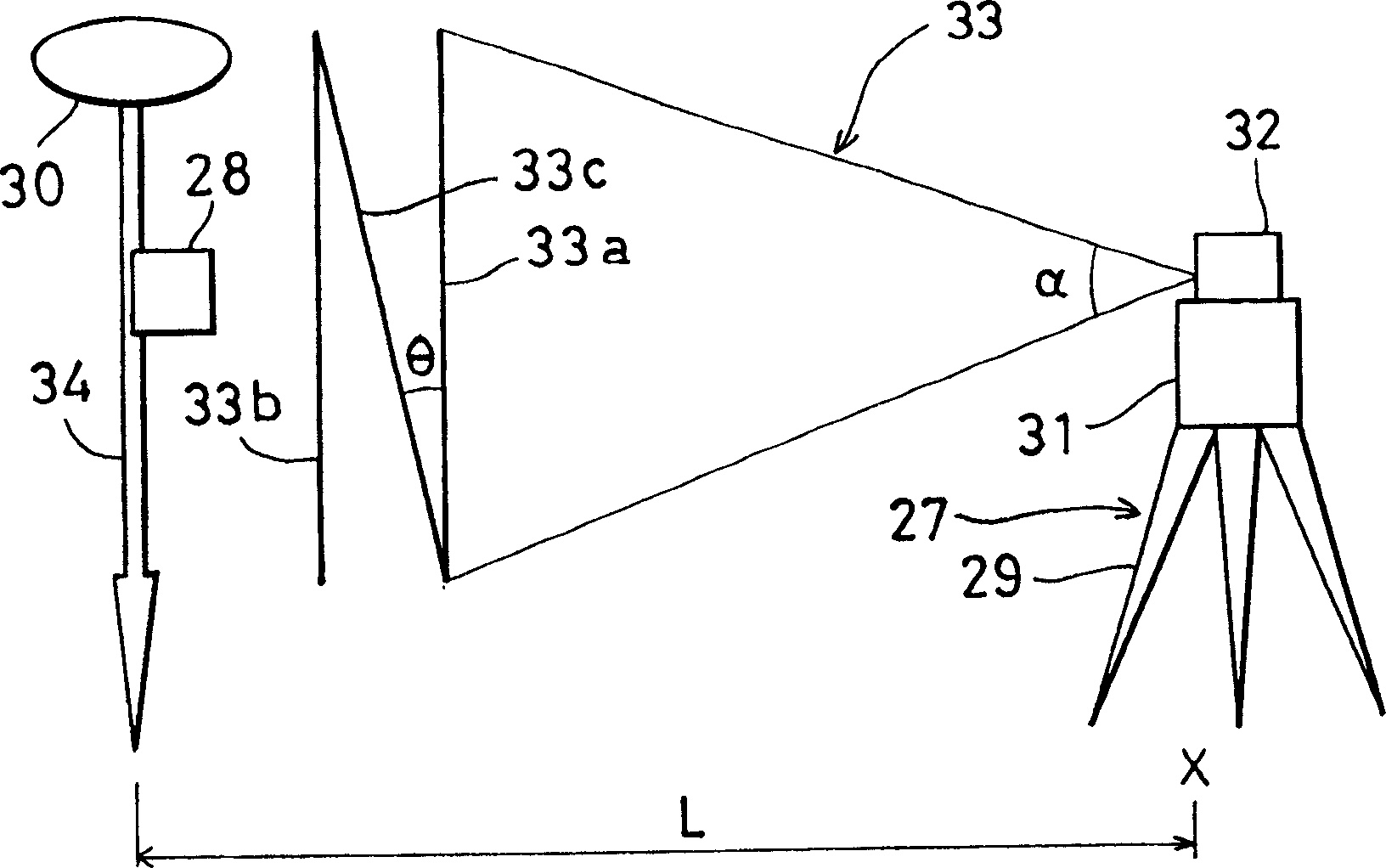
[0044] First, use figure 1 A working position measuring device according to the present invention will be schematically described.

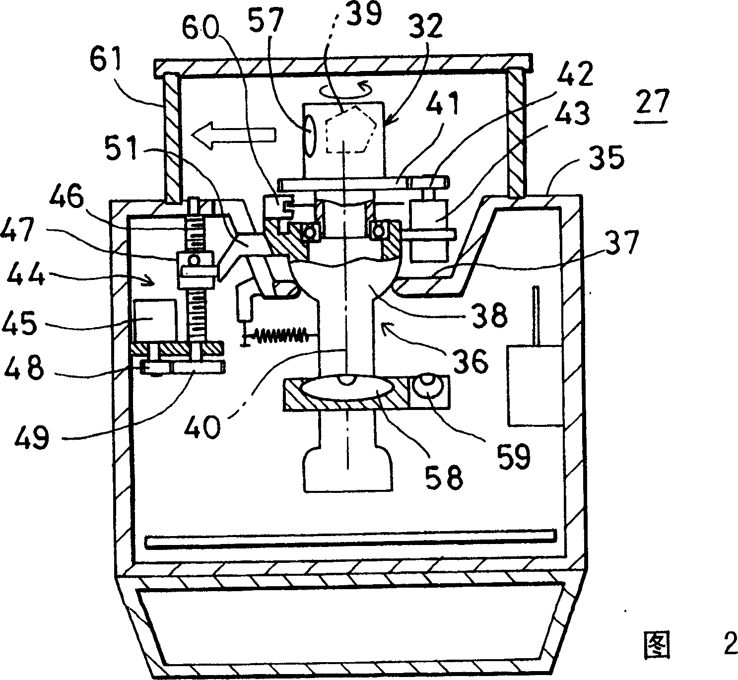
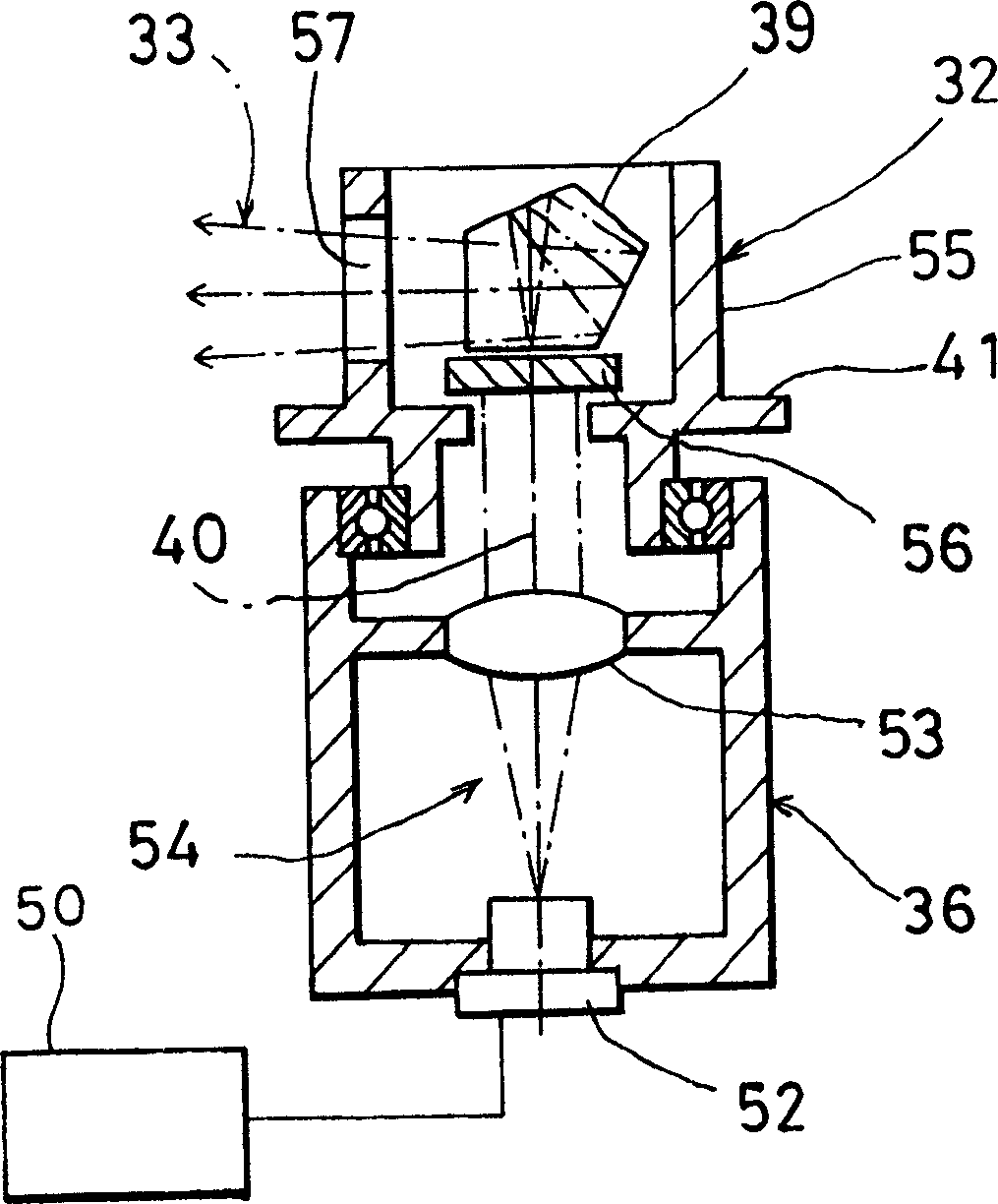
[0045] This working position measuring device includes, as a basic structure, a rotating laser device 27 for rotating and emitting a fan beam, and a laser receiving sensor device 28 for receiving the fan beam.

[0046] The tripod 29 is installed so as to roughly coincide with a generally known point X, and the above-mentioned rotating laser device 27 is attached to the tripod 29 . The rotary laser device 27 has a main body portion 31 and a rotating portion 32 provided on the main body portion 31 in a freely rotatable manner, and irradiates a laser beam 33 in rotation through the above rotating portion 32 . The above-mentioned laser receiving sensor device 28 is held by the necessary supporting mechanism. figure 1 It shows an embodiment of a devi...


PUM


Abstract

A working position measuring system, comprising a rotary laser device for irradiating and rotating a laser beam and a photodetection sensor device for receiving the laser beam and for detecting a working position, wherein the rotary laser device comprises a laser projector for projecting at least two fan-shaped beams with at least one beam tilted, and the photodetection sensor device comprises at least one photodetection unit for receiving the fan-shaped beams and an arithmetic unit for calculating an elevation angle relative to the rotary laser device based on photodetection signals produced when the photodetection unit receives the light beam.

Description

technical field [0001] The invention relates to a working position measuring device which rotates and irradiates a laser beam and measures the working position according to the receiving state of the laser beam. Background technique [0002] In the prior art, a typical device for rotating and emitting a laser beam to form a reference plane includes a rotating laser device and a laser receiving device for receiving the laser beam. [0003] The rotating laser device is a device that rotates and irradiates a laser beam in a point shape so that the beam forms a reference plane. For example, the laser beam is rotated and irradiated in the horizontal plane to form a horizontal reference plane; the laser beam is rotated and irradiated in a vertical plane to form a vertical reference plane; the laser beam is rotated and irradiated in an inclined plane to form an inclined reference plane. [0004] The laser receiving device is a device that has a light receiving unit that receives a...

Claims


Application Information

Patent Timeline
Patent Type & Authority Applications(China)
IPC IPC(8): G01B11/03G01C15/00G01S5/14G01S5/16
CPCG01S5/0072G01S5/16G01S19/43G01C15/002
Inventor 大友文夫大佛一毅林邦广
Owner KK TOPCON
Why Eureka
Try Eureka