Wiring harness and wire harness manufacturing method

A wire harness and wire technology, applied in the field of wire harnesses, can solve the problems of difficulty in reducing the cost of manufacturing wire harnesses and automation of assembly processes.

Inactive Publication Date: 2004-07-14
YAZAKI CORP
View PDF2 Cites 13 Cited by
  • Summary
  • Abstract
  • Description
  • Claims
  • Application Information

AI Technical Summary

Problems solved by technology

[0022] When crimp terminals and crimp terminals are arranged intermingled with each other, it will be difficult to automate the assembly process of assembling the connectors 101, 102
Therefore, it is difficult to reduce the cost of manufacturing the wire harness

Method used


Image

  • Wiring harness and wire harness manufacturing method
  • Wiring harness and wire harness manufacturing method
  • Wiring harness and wire harness manufacturing method

Examples


Embodiment Construction

[0056] Referring to the accompanying drawings, the embodiments of the present invention will be described in detail below. Herein, in the process of explaining the following embodiments, the same reference numerals are used to designate the same components in order to simplify or omit the corresponding explanations.

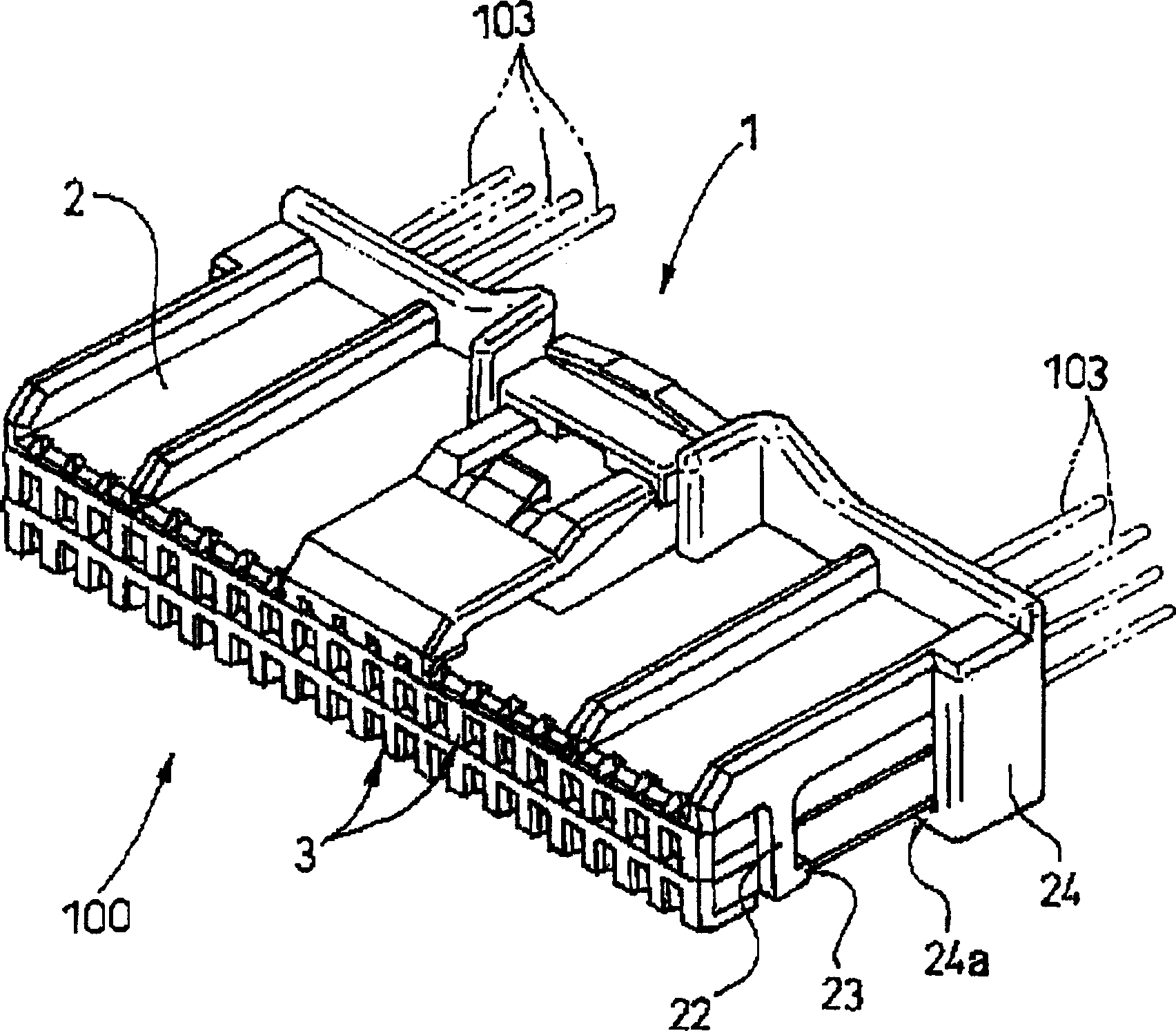
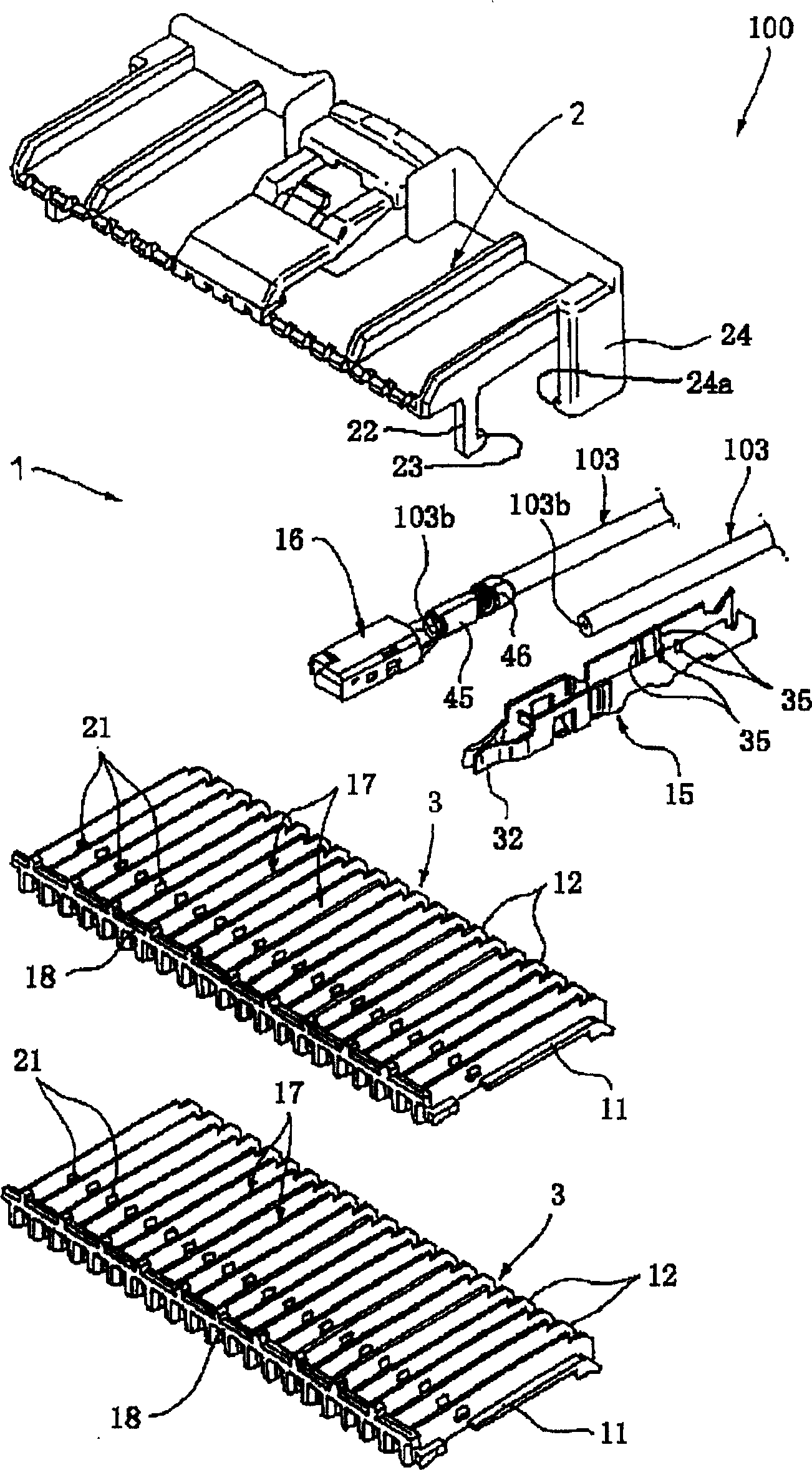
[0057] Such as figure 1 with 2 As shown in , the wire harness 100 according to the first embodiment of the present invention includes a connector 1 for accommodating a plurality of crimp terminals 15 and crimp terminals 16, wherein the crimp terminals 15 and crimp terminals 16 are respectively connected to a large number of electric wires 103 connections.

[0058] The connector 1 includes insulating housings 3 , 3 , in which crimp terminals 15 or crimping terminals 16 can be arranged separately, and a cover 2 capable of fixing the insulating housings 3 , 3 .

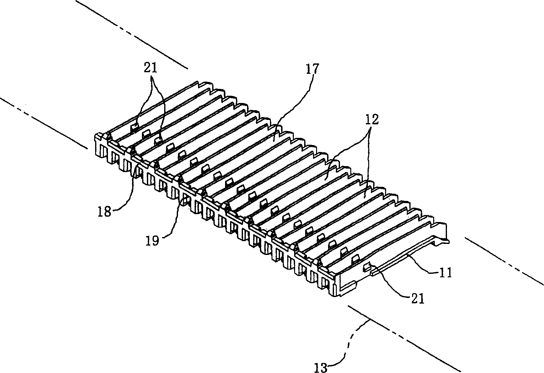
[0059] Such as image 3 As shown in , the insulating case 3 has partition walls 12 , and these part...


PUM

PropertyMeasurementUnit
diameteraaaaaaaaaa

Abstract

There are provided a wire harness and a method of manufacturing the wire harness capable of reducing the assembling cost. The wire harness includes: an insulating housing (3), on the board (11) of which partition walls (12) are arranged in parallel with each other; a cover member (2) capable of holding the insulating housing (3); a large number of pressure-connecting terminals (15) and crimping terminals (16) respectively arranged along the partition walls (12); and a large number of electric wires (103) respectively connected to the pressure-connecting terminals (15) and crimping terminals (16). The wire harness is formed by conducting the manufacturing steps of: a pressure-connecting terminal inserting step in which the pressure-connecting terminals (15) are arranged between the partition walls (12); a pressure-connecting step in which the electric wires (103) are connected with the pressure-connecting terminals (15); a crimping step in which the crimping terminals (16) are arranged between the partition walls (12) after the electric wires are connected with the crimping terminals (16); and a cutting step in which the material insulating housing (13) is cut into a predetermined length, wherein these steps are conducted in an arbitrary order, and the wire harness is formed by further conducting the manufacturing step of: a connector assembling step in which the insulating housing (3) is held by the cover member (2).

Description

technical field [0001] The present invention relates to a wire harness. For example, the present invention relates to a wire harness particularly suitable for electrically connecting control devices and electronic devices mounted on a vehicle. Background technique [0002] In general, people-carrying vehicles, as well as various other vehicles, have been automated. Depending on the degree of automation of the vehicle, various control devices such as a CPU and electronic devices are mounted on the vehicle. [0003] These control devices and electronic devices are electrically connected by wiring harnesses so that electrical power can be supplied to the devices and furthermore control signals for controlling the devices can be communicated by the devices. [0004] exist Figure 14 The wire harness 100 shown in is mainly constructed in such a way that various types of connectors, such as a male type connector 101 and a female type connector 102, are connected to each other by...

Claims


Application Information

Patent Timeline
Patent Type & Authority Applications(China)
IPC IPC(8): H01R43/00H01B7/00H01B13/012H01R13/42H01R13/514H01R43/048H01R43/20H02G1/14H02G15/02
CPCH01R43/048H01R43/20
Inventor 福田优三轮刚也望月信二
Owner YAZAKI CORP
Why Eureka
Try Eureka