Combined stator core for electic rotary machinery
A rotary machinery, combined technology, applied in the direction of electric components, manufacturing stator/rotor bodies, electrical components, etc., can solve the problems of large reluctance and reduced efficiency of electric rotating machinery, so as to reduce the reluctance and reduce the reluctance. , Improve the connection effect
- Summary
- Abstract
- Description
- Claims
- Application Information
AI Technical Summary
Problems solved by technology
Method used
Image

Examples
no. 1 example
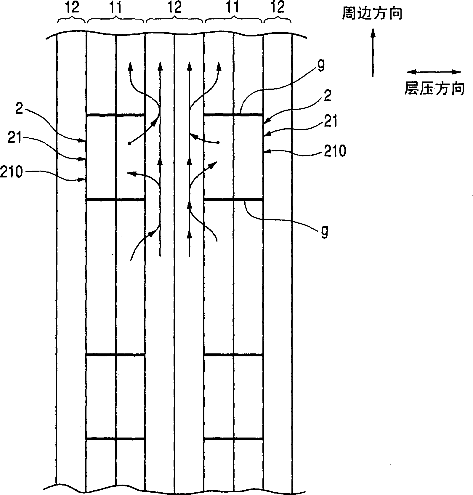
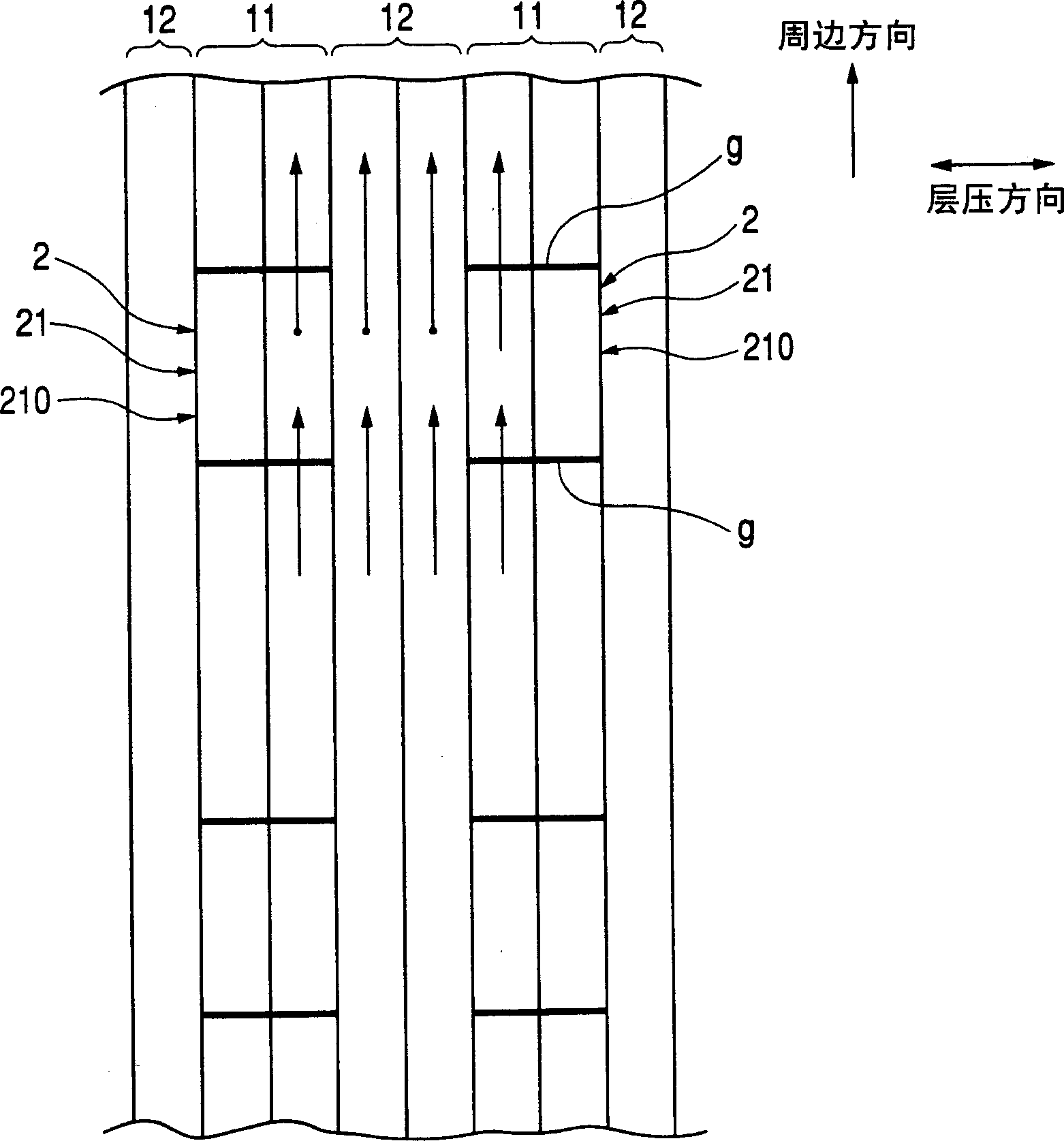
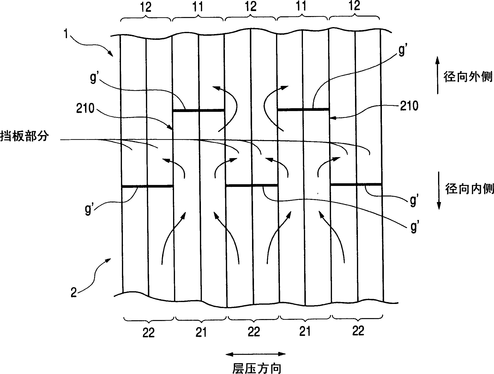
[0069] Will refer to Figure 5 with Figure 6 The combined stator core according to the first embodiment of the present invention will be explained. The combined stator core includes a cylindrical yoke 1 and a plurality of tooth blocks 2 coupled or fixed to the inner cylindrical surface of the yoke 1 at a predetermined pitch in the peripheral direction. Figure 5 Shown is a partial perspective view of a partial yoke 1 and a single tooth block 2. Figure 6 Display is display Figure 5 A partial cross-sectional view of the yoke 1 and the tooth block 2 in the axial direction (ie, the lamination direction) shown in FIG.
[0070] The yoke 1 includes a first ring plate 11 and a second ring plate 12, and the first ring plate 11 and the second ring plate 12 are alternately laminated to form a multilayer body. Each of the first annular plate 11 and the second annular plate 12 is manufactured from a single dish-shaped electromagnetic steel plate. The tooth block 2 includes first teeth 21 an...
no. 2 example
[0081] According to the first embodiment described above, the tooth blocks 2 are separated from each other. However, such as Figure 13 As shown in the figure, it is possible to connect two or more identical teeth (ie, the first tooth 21 or the second tooth 22) to the overhanging flange 25 of the tooth block 2 to narrow the groove. The overhanging flange 25 protrudes from the inner radial end of the tooth block 2. Preferably, as shown in Fig. 14, the overhanging flange 25 has a narrow portion 25' in the center of the peripheral direction, wherein the radial width of the flange 25 is narrowed to reduce the leakage of magnetic flux. In addition, such as Figure 15 with Figure 16 As shown in, it is preferable to connect a pair of first teeth 21 and second teeth 22 or more. In addition, preferably as Figure 17 with Figure 18 As shown in, a combination of a single second tooth 22 and two (or more) consecutive first teeth 21 is used to form the tooth block 2. Figure 18 Shows Figure ...
no. 3 example
[0083] Figure 19 Shown is a view of another embodiment of the present invention. According to this embodiment, each of the concave portion 110 and the convex portion 210 has a peripheral direction width that continuously decreases in the radial direction toward the outside. This arrangement effectively prevents the convex portion 210 from being blocked by the sharp edge of the concave portion 110 when the convex portion 210 is inserted into the concave portion 110 for the first time. The second annular plate 12 also preferably has a small recessed portion, and the first teeth 21 have a small convex portion coupled or fitted into the small recessed portion of the second annular plate 12.
[0084] Modified embodiment
[0085] The first ring plate 11, the second ring plate 12, the first teeth 21 and the second teeth 22 are formed by one or more electromagnetic steel plates.
PUM
 Abstract
Description
Claims
Application Information