Electric connector

A technology for electrical connectors and electrical contacts, applied in the directions of connections, circuits, and components of connecting devices, etc., can solve problems such as cables hooking on obstacles, cable damage, and decreased connector engagement force and snapping feeling.

Inactive Publication Date: 2004-08-04
SHIMANO INC
View PDF0 Cites 8 Cited by
  • Summary
  • Abstract
  • Description
  • Claims
  • Application Information

AI Technical Summary

Problems solved by technology

The problem with such non-releasable electrical connectors is that the cable can snag obstacles, possibly causing the rider to lose control of the bike and severely damage the cable
However, when the electrical connector is exposed to various temperature changes, this causes the components of the electrical connector to expand or contract according to the temperature change
This is a particular problem when electrical connectors are snap-fit
In particular, the engaging force and snapping feeling between mated connectors deteriorates when exposed to various temperature changes for a long time

Method used


Image

  • Electric connector
  • Electric connector
  • Electric connector

Examples


Embodiment Construction

[0025] Selected embodiments of the present invention will now be described with reference to the accompanying drawings. It will be apparent to those skilled in the art from the disclosure that the following descriptions of the embodiments of the present invention are illustrative only and not intended to limit the scope of the invention as defined by the appended claims and other equivalents. invention.

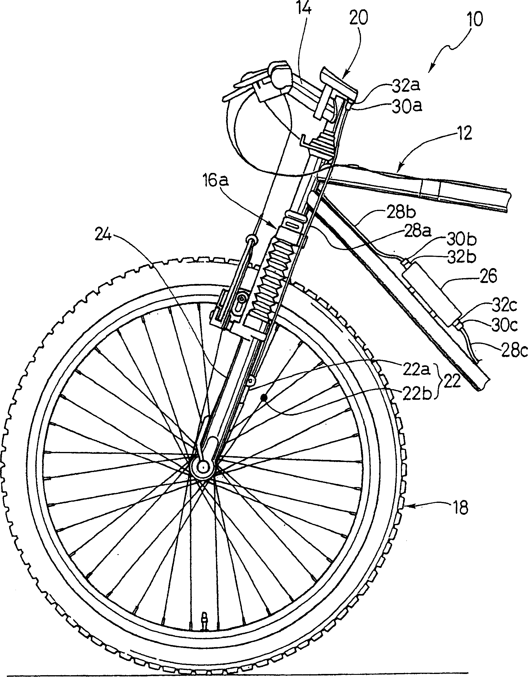
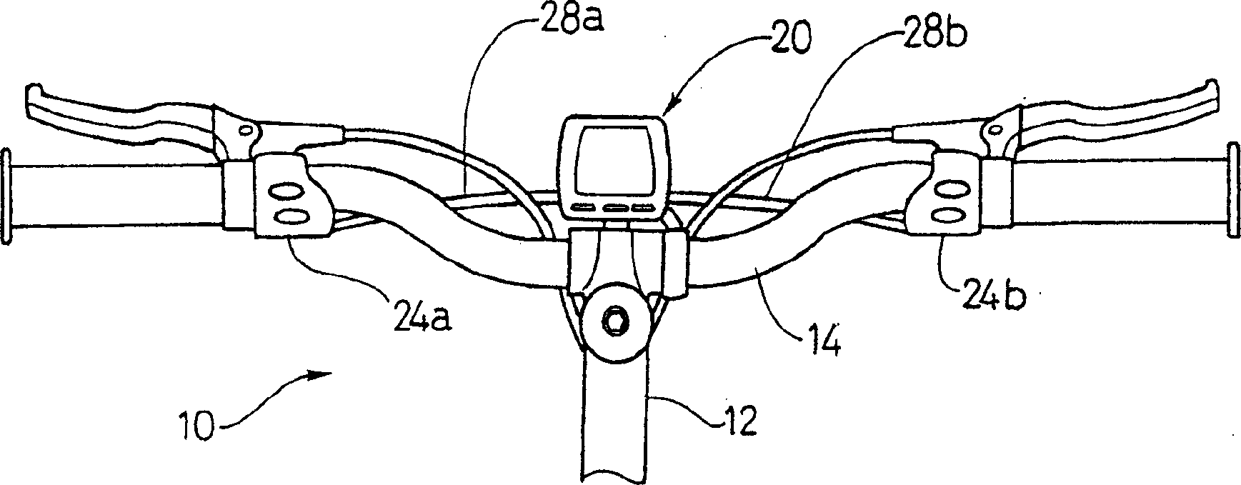
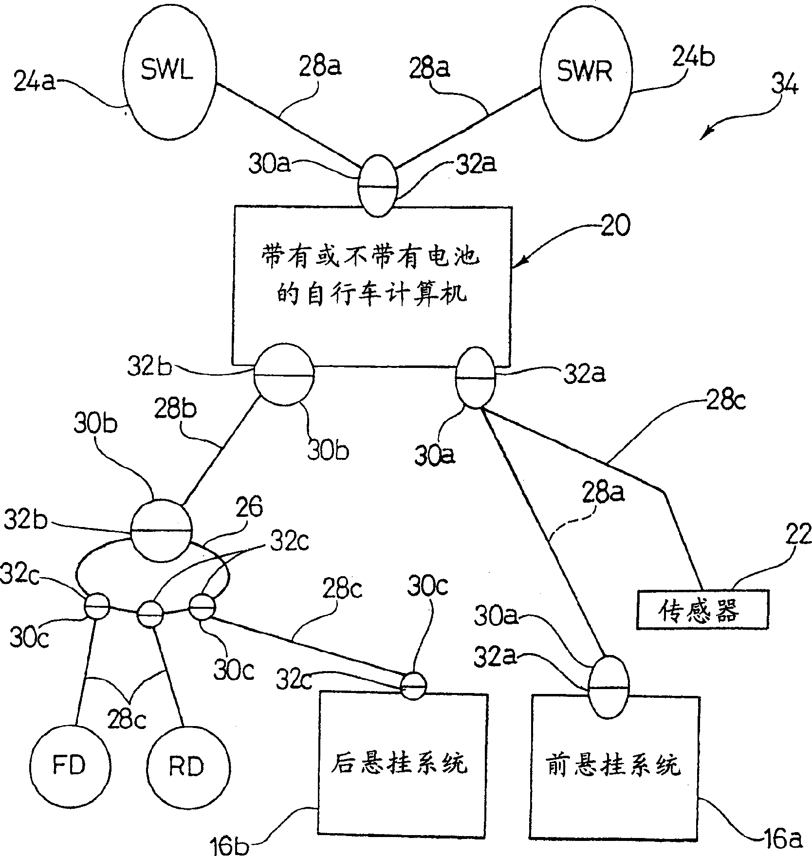
[0026] see first figure 1 and figure 2 , wherein the front of an electronically controlled bicycle 10 is shown to illustrate the present invention. The present invention relates to electrical connections between electronic control components of bicycle 10 . Thus, the bicycle 10 and its various components are well known in the art, except for the electrical connections between the electronic control components. As such, bicycle 10 and its individual components will not be described or described in detail herein, except for those pertaining to the present invention. Addit...


PUM


Abstract

Various electrically controlled devices of a bicycle are electrically coupled together by multi-conductor electrical cords. Preferably, the ends of the electrical cords have an electrical connector that mates with a corresponding electrical connector of an electrically controlled device. The electrical connectors are designed to be coupled together by a snap fit. Each electrical connector attached to the end of the electrical cord has an electrical contact housing with electrical contacts and an outer casing molded about the electrical contact housing to form a tubular portion radially spaced from the outer end of the electrical contact housing. A retaining ring is located in an annular groove formed in an exterior surface of the outer casing to provide an additional coupling force. Preferably, an annular sealing member formed of a resilient and compressible material is located in an annular space formed between the tubular portion and the electrical contact housing.

Description

technical field [0001] The invention relates to an electrical connector. In particular, the present invention relates to an electrical connector that mates with other electrical connectors by snap fit. Background technique [0002] Cycling has gradually become a popular recreational activity and a mode of transportation. In addition, cycling has become a very popular competitive sport for both amateurs and professional athletes. Whether the bicycle is used for recreational activities, transportation or competition, the bicycle industry is constantly improving the various components of the bicycle. In particular, manufacturers of bicycle components are constantly improving the performance, reliability and appearance of individual components. [0003] In recent years, bicycles have come with electronically driven transmissions with smoother shifting. These electronic drive transmissions include a rear multi-stage sprocket assembly with a motorized rear derailleur and a fro...

Claims


Application Information

Patent Timeline
Patent Type & Authority Applications(China)
IPC IPC(8): B62J99/00B62J11/19H01R13/46H01R13/52H01R13/627
CPCH01R13/6277H01R13/5219
Inventor 福田雅彦
Owner SHIMANO INC
Why Eureka
Try Eureka