
Relief for forming layer

A convex and tiny technology, applied in applications, coatings, printing plates, etc., can solve the problems that the organic light-emitting layer 22 is too thin, it is difficult to print, and it is difficult to print highly fine patterns

Inactive Publication Date: 2004-08-11
KOMURA TECH
View PDF1 Cites 16 Cited by
  • Summary
  • Abstract
  • Description
  • Claims
  • Application Information

AI Technical Summary

Problems solved by technology

However, even simply using the Figure 8 The general letterpress R0 shown is often too thin to print the organic light-emitting layer 22, and it is difficult to print the thickness of the organic light-emitting layer 22 to provide sufficient luminous efficiency, and it is also difficult to print a highly detailed pattern.

Method used


Image

  • Relief for forming layer
  • Relief for forming layer
  • Relief for forming layer

Examples


Embodiment 1

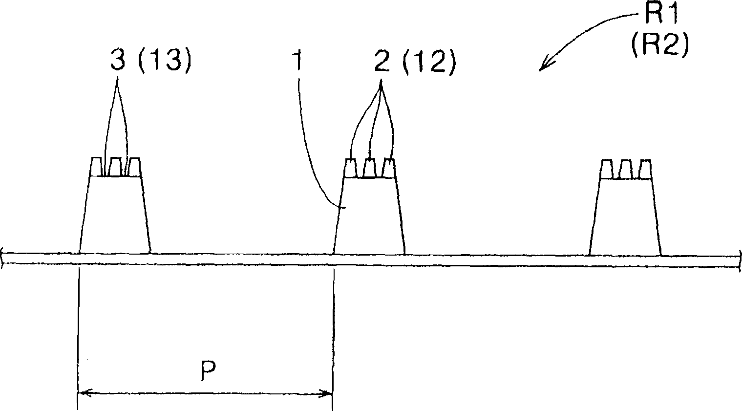
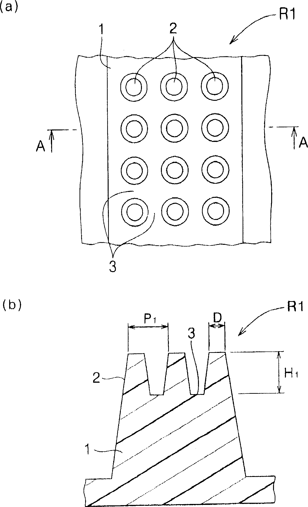
[0041] Prepare a representation such as figure 1 The indicated layer is formed with relief R1. This relief plate R1 for layer formation was manufactured in the same manner as above using liquid photocurable resin (manufactured by Asahi Kasei Co., Ltd.) 7 as a material. In addition, the dimensions of the microprotrusions 2 and the like of the relief plate R1 for layer formation are set as follows.

[0042] · Micro protrusion 2: height H 1 =15μm

[0043] Top surface diameter D=15μm

[0044] Pitch P between adjacent tiny protrusions 2 1 =27.5μm

[0045] The number of micro-protrusions 2 formed in the width direction of the top surface of each printing convex portion 1 = 3

[0046] Total stripe width = 70 μm (= 27.5 × 2 + 15)

[0047] ・Protrusion 1 for printing: installation pitch P=300μm

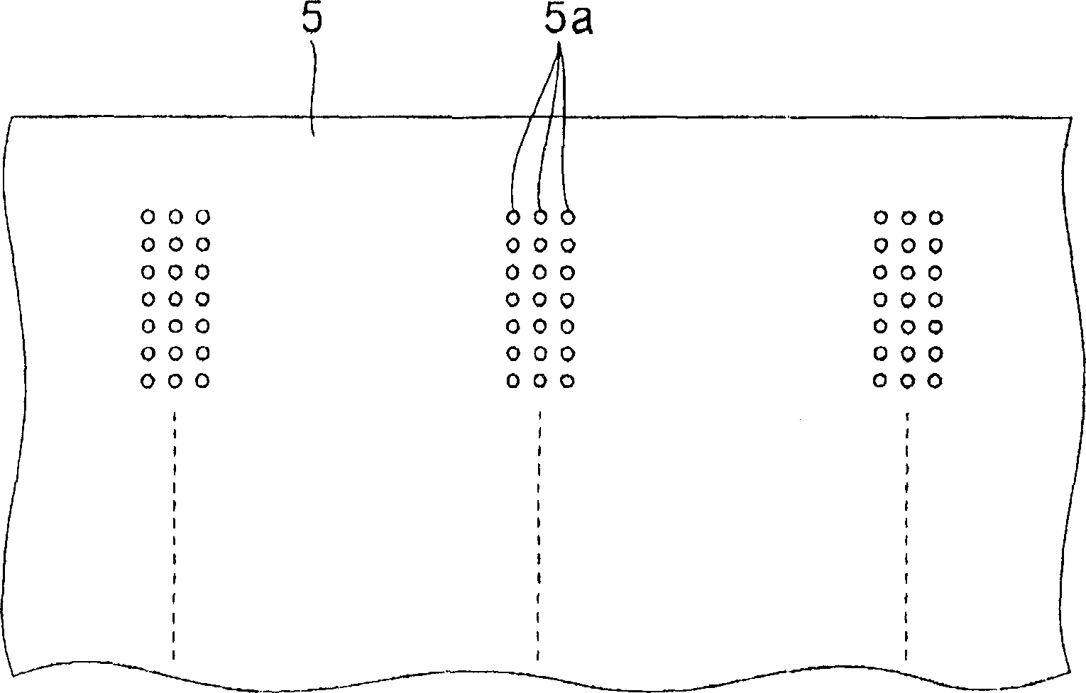
[0048] prepare a Figure 5 The indicated printing machine (manufactured by Nippon Photo Printing Machine Co., Ltd.). The metal ink roller 32 of this printing machine is made into 300...


PUM

PropertyMeasurementUnit
heightaaaaaaaaaa
viscosityaaaaaaaaaa
viscosityaaaaaaaaaa

Abstract

A layer forming relief transferring and printing an application fluid applied on printing convex portions on a printing object, the layer forming relief including printing convex portions formed as a strip, and a plurality of micro-projections distributed on top faces of the printing convex portions so as to form a groove between adjoining micro-projections for retaining the application fluid.

Description

【Technical field】 [0001] The present invention relates to a relief plate for layer formation, which is used for printing thin layers such as an organic light-emitting layer of organic electroluminescence (hereinafter referred to as "organic EL"), a color filter plate of a liquid crystal panel, and a sealant between glass substrates. . 【Background technique】 [0002] A general organic EL color display uses a black matrix (black matrix) 21 to pattern the surface of a flat glass substrate 20 in a small area, and stack an anode and an organic light-emitting layer sequentially on the surface of the glass substrate 20 in each small area. 22 and the cathode to form a laminate (refer to Figure 6 : Figure 6 The anode and the cathode are not shown), and a flat-plate-shaped sealant is made to cover this laminated body and fix it. Then, the materials that can emit light into red (R), green (G), and blue (B) colors in the organic light-emitting layer 22 are neatly arranged in each sma...

Claims


Application Information

Patent Timeline
Patent Type & Authority Applications(China)
IPC IPC(8): G02B5/20B05C1/02B41C1/00B41M1/02B41N1/06B41N1/12G02F1/1335G02F1/1339H01L51/50H05B33/10
CPCB41M1/02Y10T428/2457B41N1/12Y10T428/24479B41C1/00Y10T428/1064C09K2323/051A47G19/025A47G2400/064
Inventor 天野正典西山聪
Owner KOMURA TECH
Learn More