Internal multiband antenna

A multi-band, antenna technology, applied in antennas, resonant antennas, antenna components, etc., can solve the problem of not saving space, and achieve the effect of good radiation characteristics, small space, and low production cost

Active Publication Date: 2004-08-11
L K PROD OY
View PDF0 Cites 10 Cited by
  • Summary
  • Abstract
  • Description
  • Claims
  • Application Information

AI Technical Summary

Problems solved by technology

However with figure 1 Little or no space savings compared to the structure shown
Another disadvantage is that this antenna structure will only have one operating frequency band

Method used


Image

  • Internal multiband antenna
  • Internal multiband antenna
  • Internal multiband antenna

Examples


Embodiment Construction

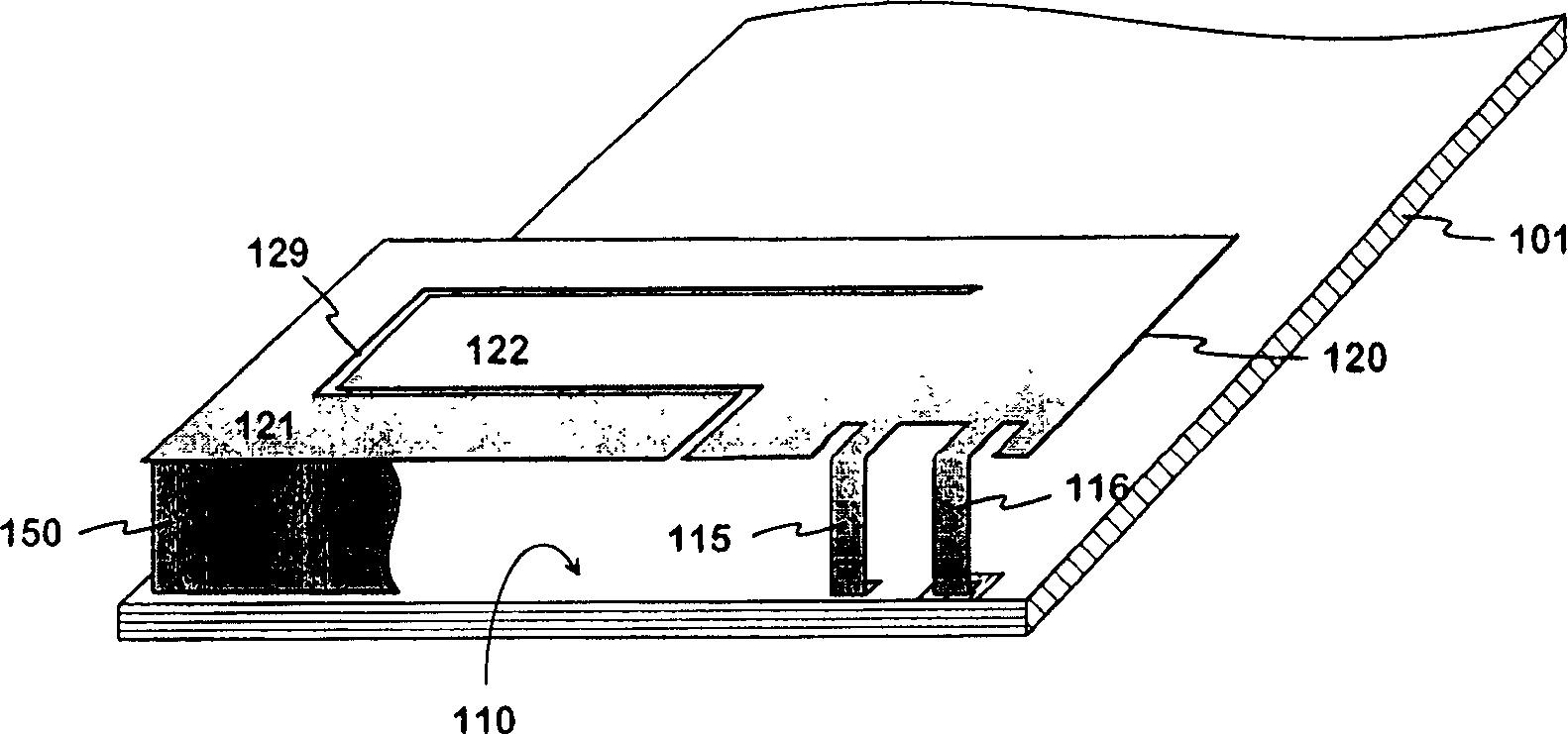
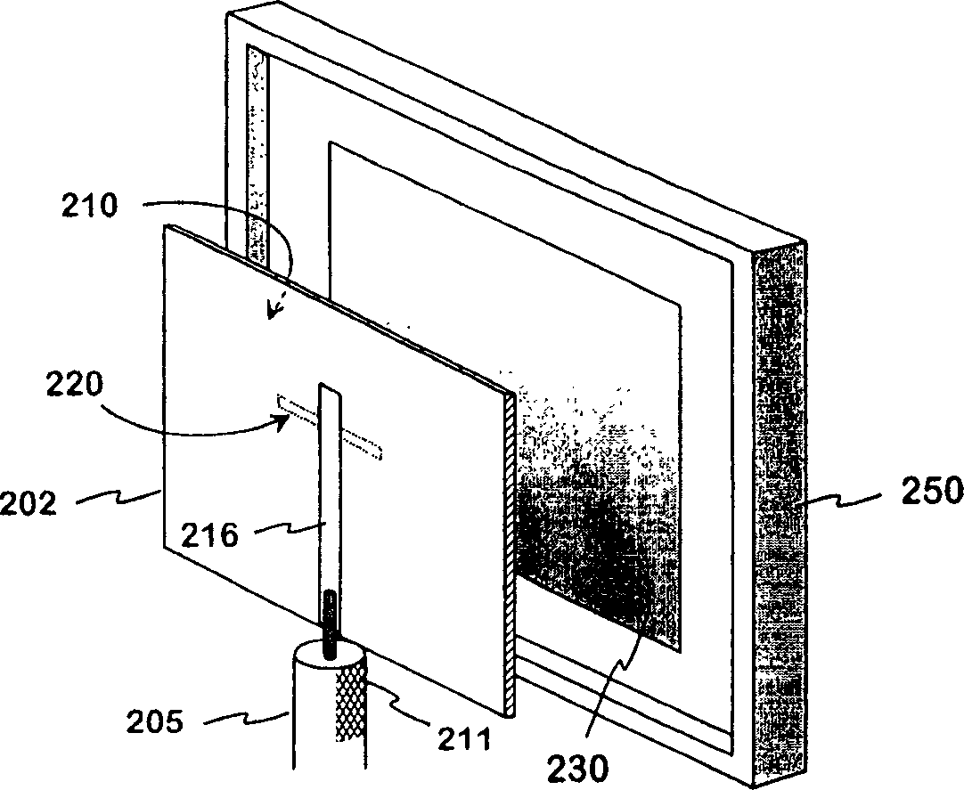
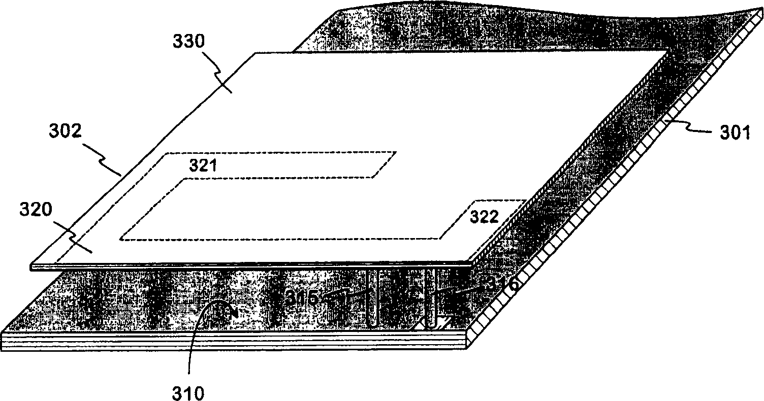
[0021] Figure 3a -c gives an example of an internal multi-band antenna according to the invention. Figure 3a The antenna structure is given from the angle of the radiating element side in . A circuit board 301 of a wireless device can be seen in the figure, wherein the conductive upper surface of the circuit board serves as a ground plane 310 for the antenna. There is a parallel insulating plate 302 on the circuit board, the upper surface of which is covered with a conductive layer, and serves as the radiating element 330 of the antenna. This insulating plate is hereinafter referred to as an antenna plate. exist Figure 3a There are antenna feed elements 320 on the lower surface of the antenna panel 302 depicted in dashed lines. This is a strip conductor running near the edge of the antenna panel 302, one end reaching the central area of ​​the antenna panel. There is only electromagnetic coupling between the radiating element and the feeding element. The antenna plate ...


PUM


Abstract

An internal multiband antenna intended to be used in small-sized radio devices and a radio device having an antenna according to the invention. The radiating element (330) of the antenna is a conductive part in the cover of the radio device or a conductive surface attached to the cover. The radiating element is fed electromagnetically by a feed element (320) connected to the antenna port. The feed element is designed (321, 322) such that it has, together with the radiating element and ground plane (310), resonating frequencies in the areas of at least two desired operating bands. In addition, the resonating frequency of the radiating element itself is arranged to fall into an operating band. Antenna matching is provided by feed element design and short-circuiting (315). The radiating element design can be based on the desired external appearance of the device, and the locations of the operating bands and antenna matching are provided through feed element design and short-circuiting. The antenna requires a relatively minor space within the device.

Description

technical field [0001] The present invention relates to internal multi-band antennas intended for use in small form factor wireless devices. The invention also relates to a wireless device equipped with the antenna of the invention. Background technique [0002] In portable wireless devices, especially mobile communication devices, the antenna is preferably placed within the cover of the device for user convenience. Internal antennas for small form factor devices are usually planar antennas for the following reasons: In this case, it is easiest to obtain satisfactory electrical characteristics for the antenna. A planar antenna includes a radiating plane and a parallel ground plane. To make impedance matching easier, the radiating and ground planes are usually connected to each other at appropriate points via shorting conductors to create a planar inverted-F antenna (PIFA). [0003] figure 1 A generally known PIFA type internal multiband antenna is given in . The figure ...

Claims


Application Information

Patent Timeline
Patent Type & Authority Applications(China)
IPC IPC(8): H01Q1/24H01Q1/38H01Q5/00H01Q5/10H01Q5/371H01Q9/04H01Q19/00
CPCH01Q1/243H01Q9/0421H01Q5/371H01Q5/0058H01Q9/0457H01Q1/38H01Q9/0442H01Q19/005H01Q9/0414
Inventor H·科尔瓦
Owner L K PROD OY
Why Eureka
Try Eureka