Power transmission mechanism of sewing machine

A power transmission mechanism and sewing machine technology, applied in the direction of sewing machine components, sewing machine needle holders, sewing machine control devices, etc., can solve the problems of increasing the number of parts, increasing manufacturing costs, and polluting sewing products

Inactive Publication Date: 2004-08-18
JUKI CORP
View PDF0 Cites 6 Cited by
  • Summary
  • Abstract
  • Description
  • Claims
  • Application Information

AI Technical Summary

Problems solved by technology

[0006] However, in the above-mentioned power transmission mechanism of the sewing machine, since the lubricating oil in a liquid state is supplied around the crank rod and around each gear, the lubricating oil will drip down and adhere to the sewing product

Method used


Image

  • Power transmission mechanism of sewing machine
  • Power transmission mechanism of sewing machine
  • Power transmission mechanism of sewing machine

Examples


Embodiment Construction

[0037] below, yes Figure 1 to Figure 5 An embodiment of the invention is shown and described.

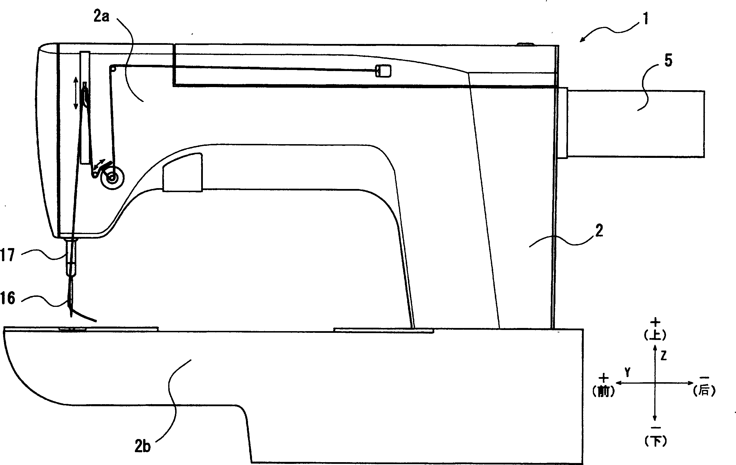
[0038] Such as figure 1 As shown, the sewing machine 1 has a sewing machine frame 2 having a substantially U-shaped outer shape when viewed from the side. The sewing machine frame 2 has a sewing machine head 2a extending forward and rearward as an upper portion of the sewing machine 1 and a sewing machine floor portion 2b extending forward and rearward as a lower portion of the sewing machine 1 .

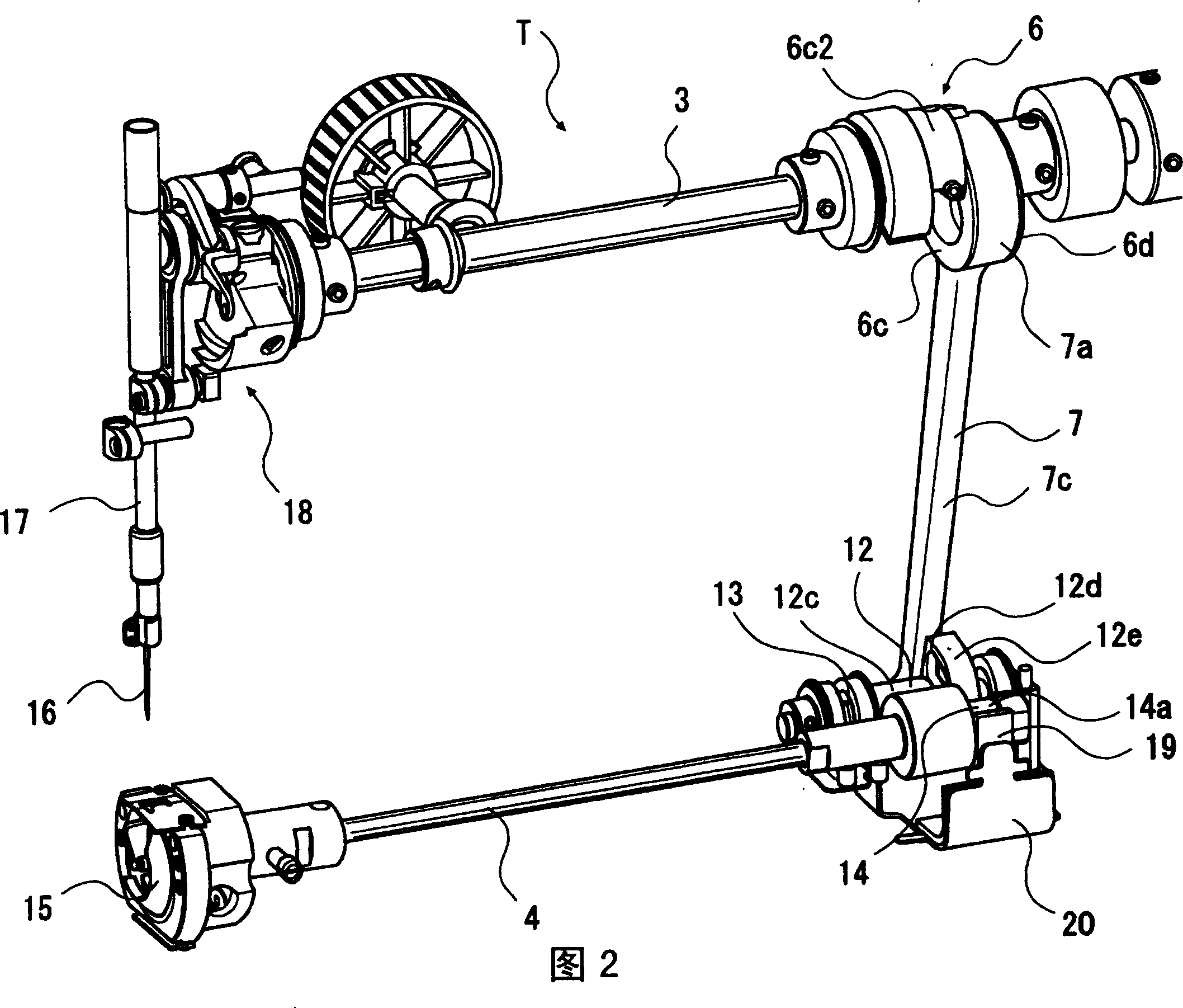
[0039] As shown in FIG. 2 , the sewing machine 1 is provided with a power transmission mechanism T in a sewing machine frame 2 and has a rotatable upper shaft 3 and a lower shaft 4 extending forward and backward. The upper shaft 3 is arranged inside the sewing machine head portion 2a, and the lower shaft 4 is arranged inside the sewing machine bottom plate portion 2b.

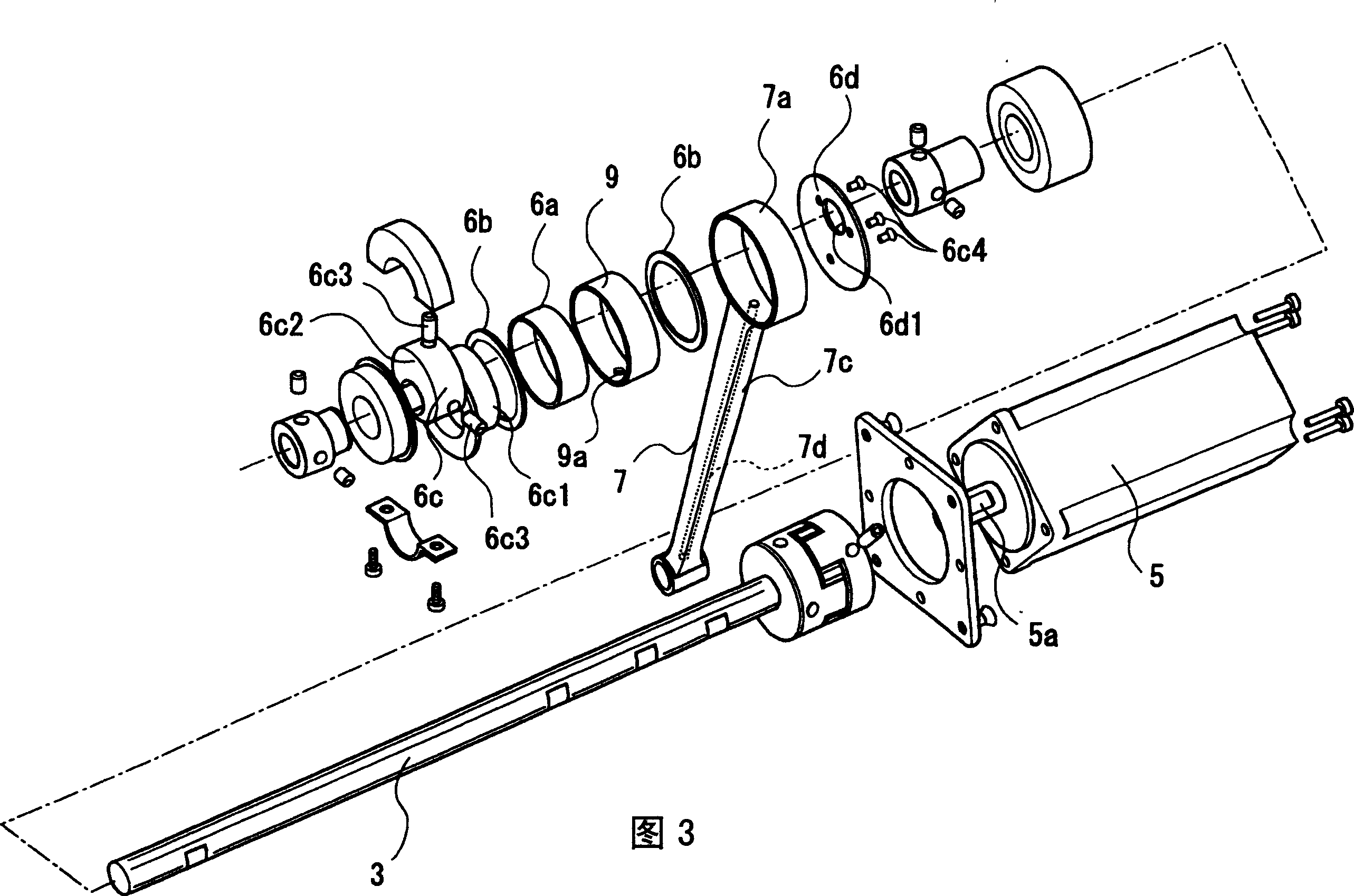
[0040] Next, the power transmission mechanism T will be described with reference to FIGS. 2 to 4 .

[0041] As show...


PUM


Abstract

In the power transmission mechanism T of a sewing machine provided with a crank rod, a first gear and a second gear for dynamically connecting an upper shaft for vertically moving a sewing needle 16 and a lower shaft for swinging a shuttle, a grease holding member impregnated with grease is brought into contact with at least one of the first gear and the second gear and the grease is applied to the respective gear.

Description

technical field [0001] The present invention relates to a power transmission mechanism of a sewing machine, in particular to a freely rotatable upper shaft which enables the sewing machine needle to move up and down, and is provided with a power connection with the upper shaft through a crankshaft rod, a first gear, a second gear, etc. The lower shaft of the hook is the power transmission mechanism of the sewing machine that sews through the cooperation of the sewing machine needle and the hook. Background technique [0002] As this sewing machine, there is known a conventional sewing machine that has an upper shaft that moves the sewing machine needle up and down and a lower shaft that swings the hook, and performs sewing by the cooperative action of the sewing machine needle and the hook. The power transmission mechanism of this sewing machine has a rotatable upper shaft, a crank rod connected to the upper end side of the upper shaft, a first gear connected to the lower en...

Claims


Application Information

Patent Timeline
IPC IPC(8): D05B71/00D05B55/14D05B69/00
CPCD05B55/14D05B69/02D05B69/30D05B71/00F16N11/00
Inventor 应性宝沟渕顺也皆川忠义
Owner JUKI CORP
Why Eureka
Try Eureka