Floor type air-conditioner
An air conditioner and floor-standing technology, which is applied in air conditioning systems, heating methods, space heating and ventilation, etc., can solve problems such as uneven distribution of wind speed, uneven distribution of air speed, condensation, etc.
- Summary
- Abstract
- Description
- Claims
- Application Information
AI Technical Summary
Problems solved by technology
Method used
Image

Examples
Embodiment 1
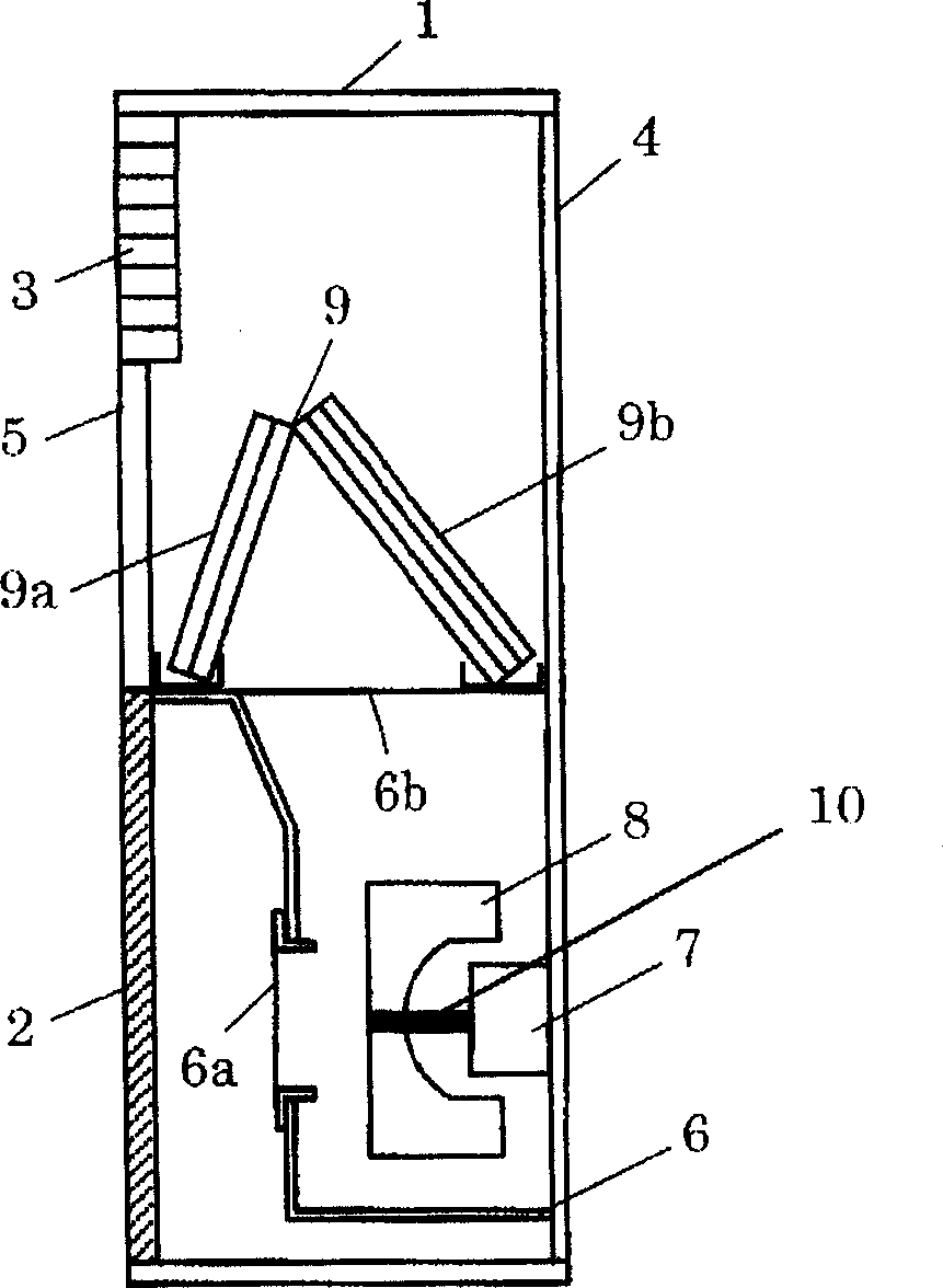
[0013] figure 1 It is a side view showing the internal structure of the floor-standing air conditioner in Embodiment 1 of the present invention. Its basic structure is the same as that of the floor-standing air conditioner in the past, and the same parts have adopted the same reference numerals, so the detailed description is omitted.
[0014] Such as figure 1 As shown, a housing 6 is installed on the lower part of the rear panel 4, and the motor 7 is installed inside the housing 6. The motor 7 is supported by the rear panel 4, and the centrifugal fan 8 is attached to the rotating shaft 10 to form an air blower. In addition, the casing 6 is composed of a casing suction port 6 a facing the main body suction port 2 and a casing exhaust port 6 b opening upward. A heat exchanger 9 is further provided above the case 6. The heat exchanger 9 has an inverted V shape and is composed of a front side heat exchanger 9a and a rear side heat exchanger 9b. Therefore, the air sucked in ...
Embodiment 2
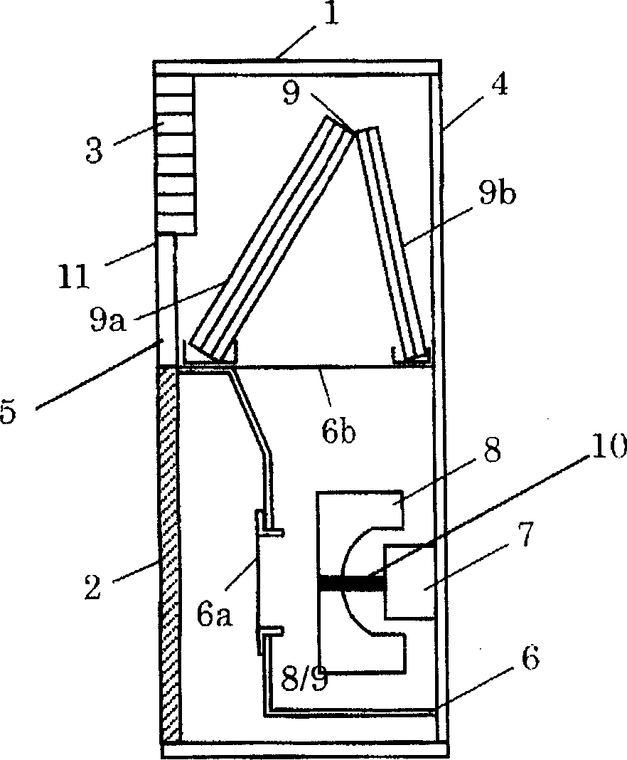
[0019] figure 2 It is a side view showing the internal structure of the floor-standing air conditioner in Embodiment 2 of the present invention.
[0020] Such as figure 2 As shown, the upper end portion of the heat exchanger 9 is disposed above the horizontal plane of the lower side 11 constituting the main body discharge port 3 . In addition, similarly to the first embodiment, the heat exchanger 9 is constructed in a convex shape (inverted V-shape) upward from the front panel 5 on the front of the main body to the rear panel 4 on the back of the main body. In addition, the installation of the centrifugal fan 8 and the like is also the same as that of the first embodiment. In this case, contrary to Example 1, the wind speed of the front side heat exchanger 9a located at the obliquely upper part of the centrifugal fan 8 is high, and the wind speed of the rear side heat exchanger 9b is low.
[0021] Therefore, in the present embodiment, the number of arrays of front-side he...
Embodiment 3
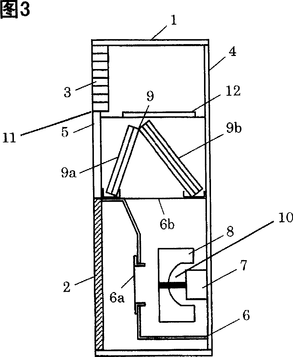
[0023] Fig. 3 is a side view showing the internal structure of the floor-standing air conditioner in Embodiment 3 of the present invention. Its basic structure is the same as that of Embodiment 1, so detailed description is omitted.
[0024] In this embodiment, the heat exchanger 9 is provided above the case exhaust port 6b, and the main body exhaust port 3 is provided above the heat exchanger 9. As shown in FIG. In addition, an electric heater 12 serving as an auxiliary heating unit is provided on a horizontal plane higher than the upper end of the heat exchanger 9 and lower than the lower side 11 constituting the main body exhaust port 3 . Therefore, by energizing the electric heater 12 in the flow path where the wind speed is uniformly distributed by the front side heat exchanger 9a and the rear side heat exchanger 9b, air with little temperature unevenness can be discharged from the main body discharge port 3, thereby Realize a comfortable indoor heating space. In additi...
PUM
 Abstract
Description
Claims
Application Information
 - R&D
- Intellectual Property
- Life Sciences
- Materials
- Tech Scout
- Unparalleled Data Quality
- Higher Quality Content
- 60% Fewer Hallucinations
Browse by: Latest US Patents, China's latest patents, Technical Efficacy Thesaurus, Application Domain, Technology Topic, Popular Technical Reports.
© 2025 PatSnap. All rights reserved.Legal|Privacy policy|Modern Slavery Act Transparency Statement|Sitemap|About US| Contact US: help@patsnap.com