Ultrasonic radiation generating device for ultrasonic therapy

A technology of ultrasonic radiation and ultrasonic therapy, which can be used in ultrasonic therapy, treatment, sounding equipment, etc., and can solve the problems of expensive phase array technology.

Inactive Publication Date: 2004-08-25
SIEMENS AG
View PDF2 Cites 4 Cited by
  • Summary
  • Abstract
  • Description
  • Claims
  • Application Information

AI Technical Summary

Problems solved by technology

[0006] The last two devices mentioned above have the disadvantage that changing the focal point requires a mechanical change in the imaging geometry
However, controlling such a phased array is technically expensive

Method used


Image

  • Ultrasonic radiation generating device for ultrasonic therapy
  • Ultrasonic radiation generating device for ultrasonic therapy
  • Ultrasonic radiation generating device for ultrasonic therapy

Examples


Embodiment Construction

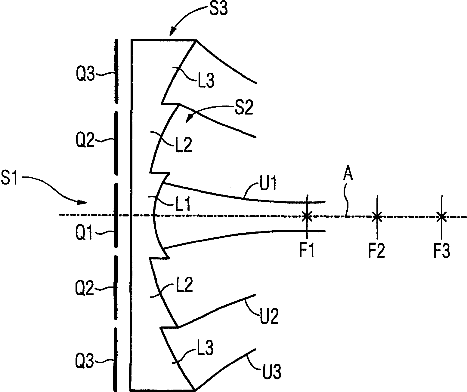
[0019] according to figure 1 , a device for generating ultrasound radiation U1, U2, U3 for ultrasound therapy comprising a plurality of ultrasound transmitters S1 to S3 coaxially arranged around a common central axis A and having emitting surfaces that are rotationally symmetrical around this axis. Each ultrasound transmitter S1 to S3 comprises an ultrasound source Q1 to Q3 with a planar emitting surface. The ultrasound source Q1 located in the middle has a disc-shaped emission surface, while the ultrasound sources Q2 and Q3 located outside each have a ring-shaped emission surface. A plano-concave acoustic lens L1 to L3 is assigned to each ultrasound source Q1 to Q3, the concave surfaces of which have different radii of curvature from each other, so that the focal points F1 to F3 belonging to the ultrasound transmitters S1 to S3 respectively share a central axis A here are located at different spatial positions from each other. The outer lenses L2, L3 are annular, while the ...


PUM


Abstract

Ultrasonic radiation generating device for ultrasonic therapy. Ultrasonic senders (S1-S3) that produce ultrasonic beams (U1-U3) having differing foci (F1-F3). Each ultrasonic sender is assigned an ultrasonic source (Q1-Q3) for focusing the ultrasonic beams (U1-U3). A close lens (L1-L3) is arranged on the emission surface of each ultrasonic source.

Description

technical field [0001] The invention relates to a device for generating ultrasound radiation for ultrasound therapy. Background technique [0002] In medical applications of high-intensity ultrasound radiation, such as in lithotripsy or in artificial pyrotherapy machines, it is required to be able to change the depth position of the focal point in the body. In addition, it is also required that the shape of the focal point matches the respective conditions of use (no calculi or the size of necrotic tumors), without changing the position of the ultrasound source relative to the body or mechanically exchanging the imaging components. [0003] A lithotripter with variable focus is disclosed, for example, in German laid-open patent application DE 37 39 390 A1. In this known lithotripter, a second pulse wave source with an annular emission surface is arranged around a first pulse wave source with a circular emission surface. An acoustic lens, which focuses the pulsed waves gene...

Claims


Application Information

Patent Timeline
IPC IPC(8): A61B17/22G10K11/30
CPCA61B17/225A61B2017/22027G10K11/30A61B17/22004
Inventor 詹斯·费尔伯恩德·格兰兹拉尔夫·南克
Owner SIEMENS AG
Why Eureka
Try Eureka