Microwave door with viewing window

A technology of microwave devices and windows, applied in the direction of microwave heating, electric heating devices, applications, etc., can solve the problems that cannot be realized optimally

Inactive Publication Date: 2004-08-25
SCHOTT AG
View PDF5 Cites 24 Cited by
  • Summary
  • Abstract
  • Description
  • Claims
  • Application Information

AI Technical Summary

Problems solved by technology

[0005] Since, on the one hand, this layer heats up to prevent condensation from forming in the window and, on the other hand, the microwave radiation is reflected back into the coo

Method used


Image

  • Microwave door with viewing window

Examples


Embodiment Construction

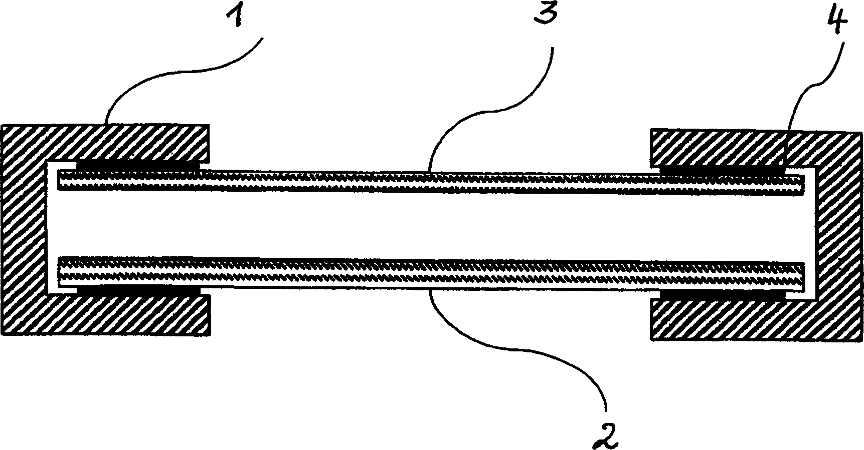
[0026] The windowed door for a microwave device shown in the figures has a metal frame 1 in which two glass panes 2, 3 are fastened spaced apart. The glass plate 3 facing the inside of the device is preferably made by the trademark Borofloat  glass, while the glass pane 2 facing the surroundings is preferably made of the trademark "Scholf  The glass panes 2, 3 are preferably glued to the metal frame 1 by means of an adhesive 4. The adhesive 4 thus ensures that the glass panes 2, 3 are inserted in a professional manner, i.e. The glass pane is supported continuously elastically and shock-absorbing.

[0027] The glass plate 3 directed towards the inside of the cooking chamber has at least one first layer that is optically transparent and absorbs microwave radiation, the absorption capacity of which is designed such that it heats up to prevent the formation of condensation water.

[0028] The first layer can be formed, for example, by a high-resistance conductive layer having ...


PUM

PropertyMeasurementUnit
Surface resistanceaaaaaaaaaa

Abstract

The microwave unit door includes a metallic door frame (1) with an interior glass pane (3) and outer glass pane (2) held spaced apart in it. To improve the observability of the interior of the microwave unit without loosing the microwave shielding effect, e.g. previously provided by a metal screen between the glass panes, and to prevent condensate formation, the interior glass pane (3) closest to the processing space (I) has at least one optically transparent electrically conductive first layer (13) with a microwave absorption capability such that it heats up to prevent condensate formation during operation. The outer glass pane (2) has at least one optically transparent electrically conductive second layer (12) reflecting microwaves passing through the first layer.

Description

technical field [0001] The invention relates to a windowed door for a microwave device according to the preamble of claim 1 . Background technique [0002] Doors for microwave units usually have a viewing window to better observe the cooking process in the microwave unit. Said window is known to comprise two glass panes of refractory glass, spaced apart in a metal frame. Since the microwave-transmitting behavior of this glass is not insignificant, a shield against microwave radiation is required in the window area within the metal frame. [0003] In the known device, the shield is made of a perforated black-painted metal plate, which is fixedly mounted in the space between the two glass plates and is in conductive contact with the metal frame. This relatively solid perforated metal plate (also known as a perforated grid plate), although shielded to the required degree from microwave radiation, significantly interferes with the view of the interior of the microwave device. ...

Claims


Application Information

Patent Timeline
IPC IPC(8): F24C15/04H05B6/76H05B6/80
CPCH05B6/6414F24C15/04H05B6/766
Inventor I·亨策S·鲍尔O·格罗斯B·舒尔泰斯
Owner SCHOTT AG
Why Eureka
Try Eureka