Magnetic isolation grid driver

A gate driver and isolation drive circuit technology, applied in the direction of output power conversion devices, electrical components, etc., can solve problems such as power failure, switch tube misconduct, and no transient characteristics

Inactive Publication Date: 2004-08-25
DELTA ELECTRONICS INC
View PDF0 Cites 12 Cited by
  • Summary
  • Abstract
  • Description
  • Claims
  • Application Information

AI Technical Summary

Problems solved by technology

Therefore, this kind of drive circuit does not have better transient characteristics, and when the power supply is turned on and off, it will cause false conduction of the switch tube, which may cause the failure of the entire power supply.

Method used


Image

  • Magnetic isolation grid driver
  • Magnetic isolation grid driver
  • Magnetic isolation grid driver

Examples


Embodiment Construction

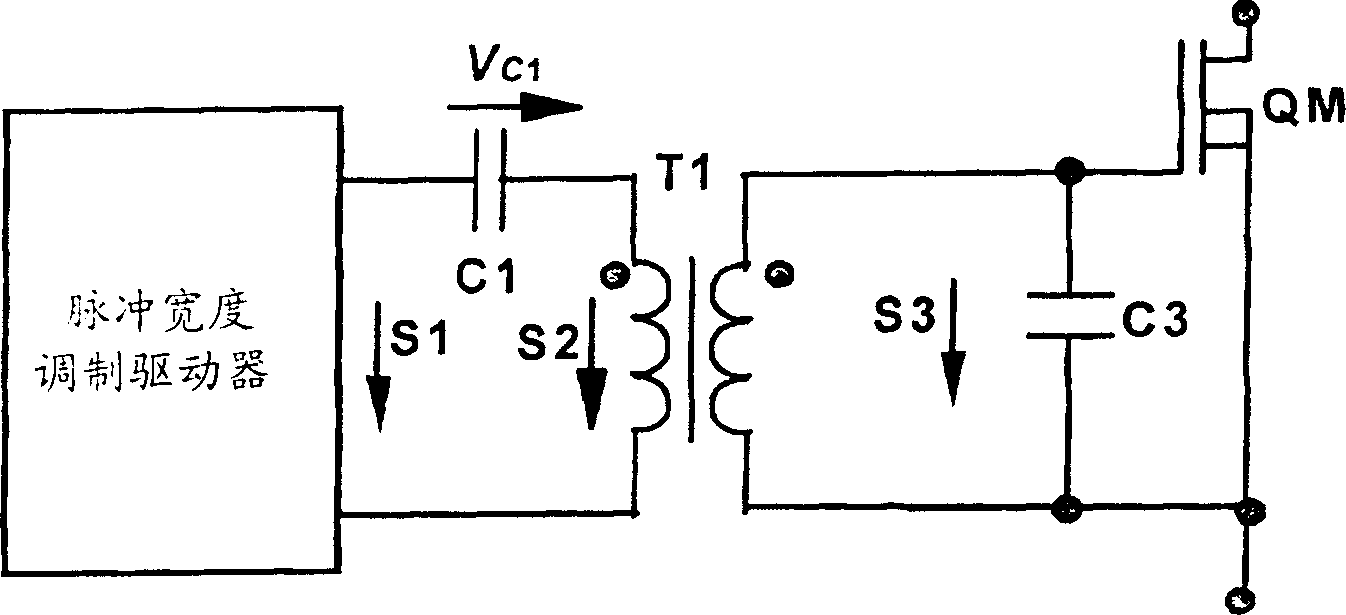
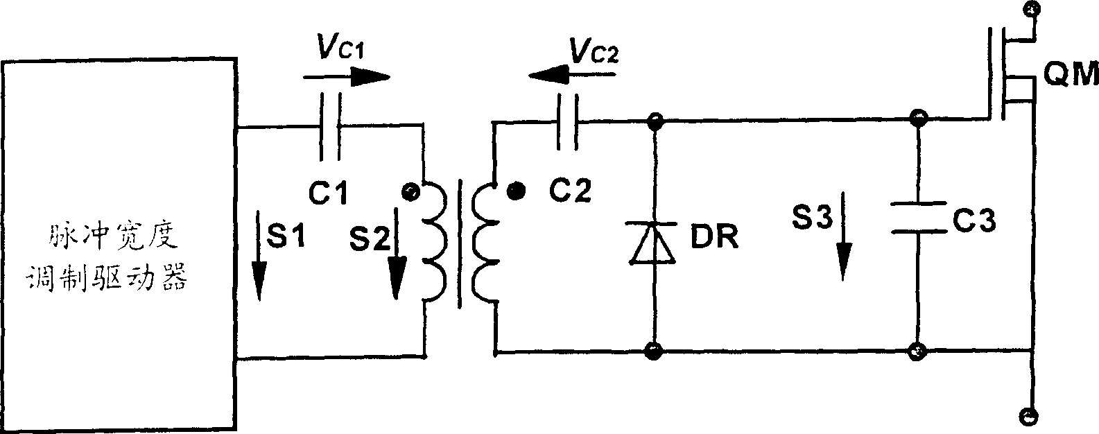
[0018] see Image 6 As shown, the figure shows the first embodiment of the magnetically isolated gate driver of the present invention. The magnetically isolated gate driver includes: a pulse width modulation driver (PWM Driver) for generating a pulse width modulation signal, a pulse isolation transformer T1 with the polarity shown in the figure, connected in series with the input and output terminals of the transformer respectively DC blocking capacitors C1, C2 and a low-power metal-oxide-semiconductor field effect transistor Q1 at the output end. Wherein the low-power metal-oxide-semiconductor field effect transistor Q1 is connected in series with the output terminal capacitor C2, its source is connected to one terminal of the output terminal, and the gate is connected to the other terminal of the output terminal, and the output terminal capacitor C2 1. The diode D1 and the low-power MOSFET Q1 form a series loop, the gate of the driven MOSFET is connected to the cathode of t...


PUM


Abstract

A magnetic isolation grating driver includes a driver generating pulse width variable signals, a pulse isolation transformer, an input capacitor serial to the input of the transformer, an output capacitor serial to output of the transformer, an output diode parallel to the output of the magnetic isolation grating driver, output small power MOS fieldistor serial to the capacitor of the output which source is connected with a terminal of the transformer output and the grating to the other, the transformer output , the output capacitor, the diode and the MOS fieldistor make up of a serial circuit.

Description

(1) Technical field [0001] The invention relates to a magnetically isolated driver, in particular to a magnetically isolated gate driver provided with a power metal oxide semiconductor field effect transistor so as to have better transient characteristics. (2) Background technology [0002] Magnetically isolated drivers can be used to drive high-end power MOSFETs. A commonly used driver circuit such as figure 1 shown. The capacitor C1 is the DC isolation capacitor at the input terminal, and the reference direction of the capacitor voltage is as follows: figure 1 As shown, T1 is an isolation transformer, QM is a driven MOSFET, and C3 is an equivalent input capacitance of QM. S1 is the output signal waveform of the pulse width modulation driver (PWM Driver), S2 is the waveform at the input end of the transformer, and S3 is the output waveform of the magnetic isolation driver. figure 1 For the working waveform of the circuit shown, please refer to figure 2 As shown, assum...

Claims


Application Information

Patent Timeline
Patent Type & Authority Applications(China)
IPC IPC(8): H02M1/08H02M1/32
Inventor 章进法王波甘鸿坚
Owner DELTA ELECTRONICS INC
Why Eureka
Try Eureka