High performance magnetron for DC sputtering systems

A technique for sputtering targets, sputter deposition, application in the setting and orientation of accelerator magnets, tilted sputtering targets and shielding

Inactive Publication Date: 2004-08-25
APPLIED MATERIALS INC
View PDF2 Cites 8 Cited by
  • Summary
  • Abstract
  • Description
  • Claims
  • Application Information

AI Technical Summary

Problems solved by technology

The invention allows horizontal orientation of workpieces

Method used


Image

  • High performance magnetron for DC sputtering systems
  • High performance magnetron for DC sputtering systems
  • High performance magnetron for DC sputtering systems

Examples


Embodiment Construction

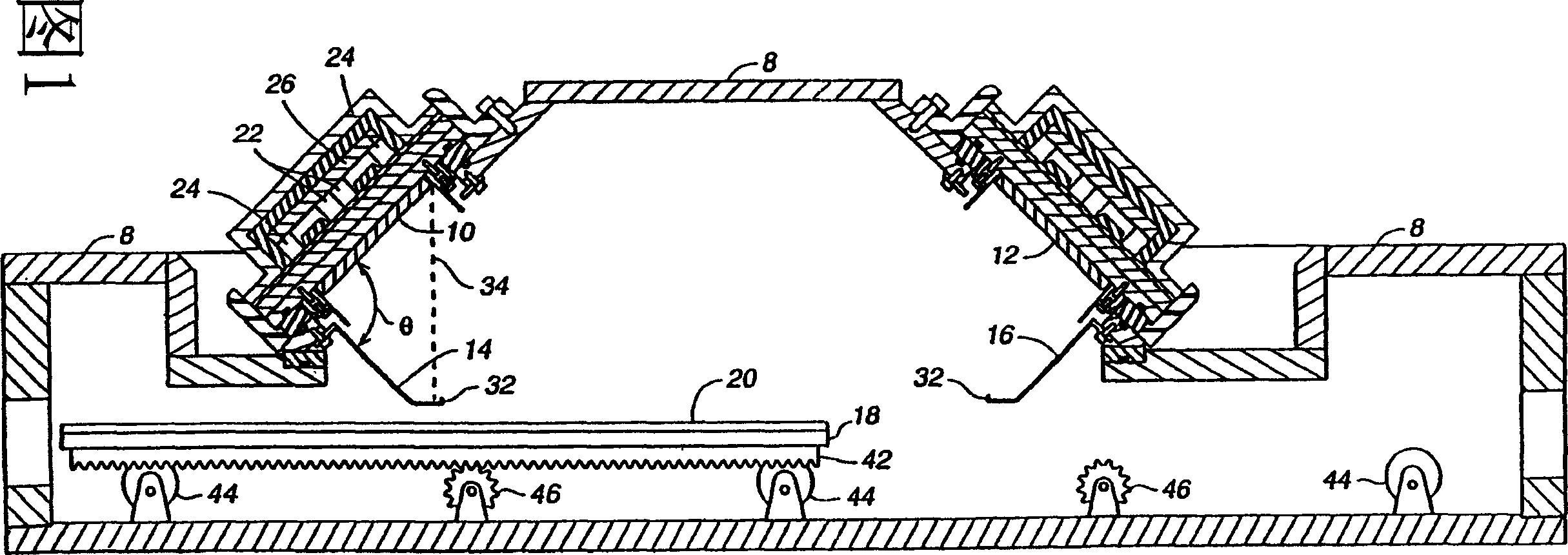
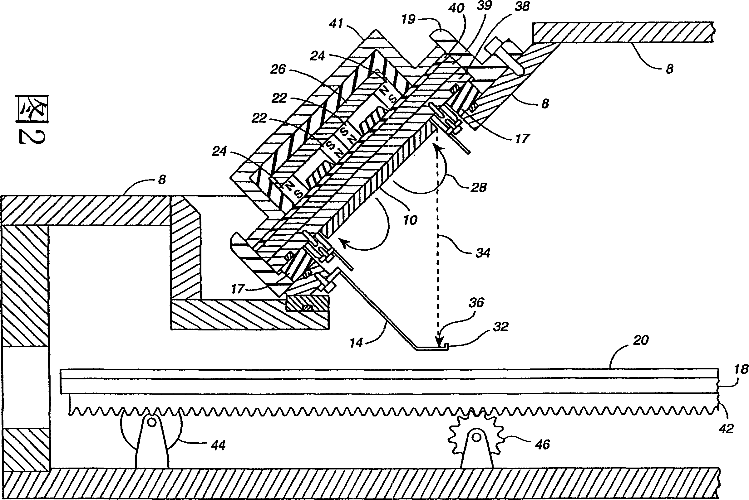
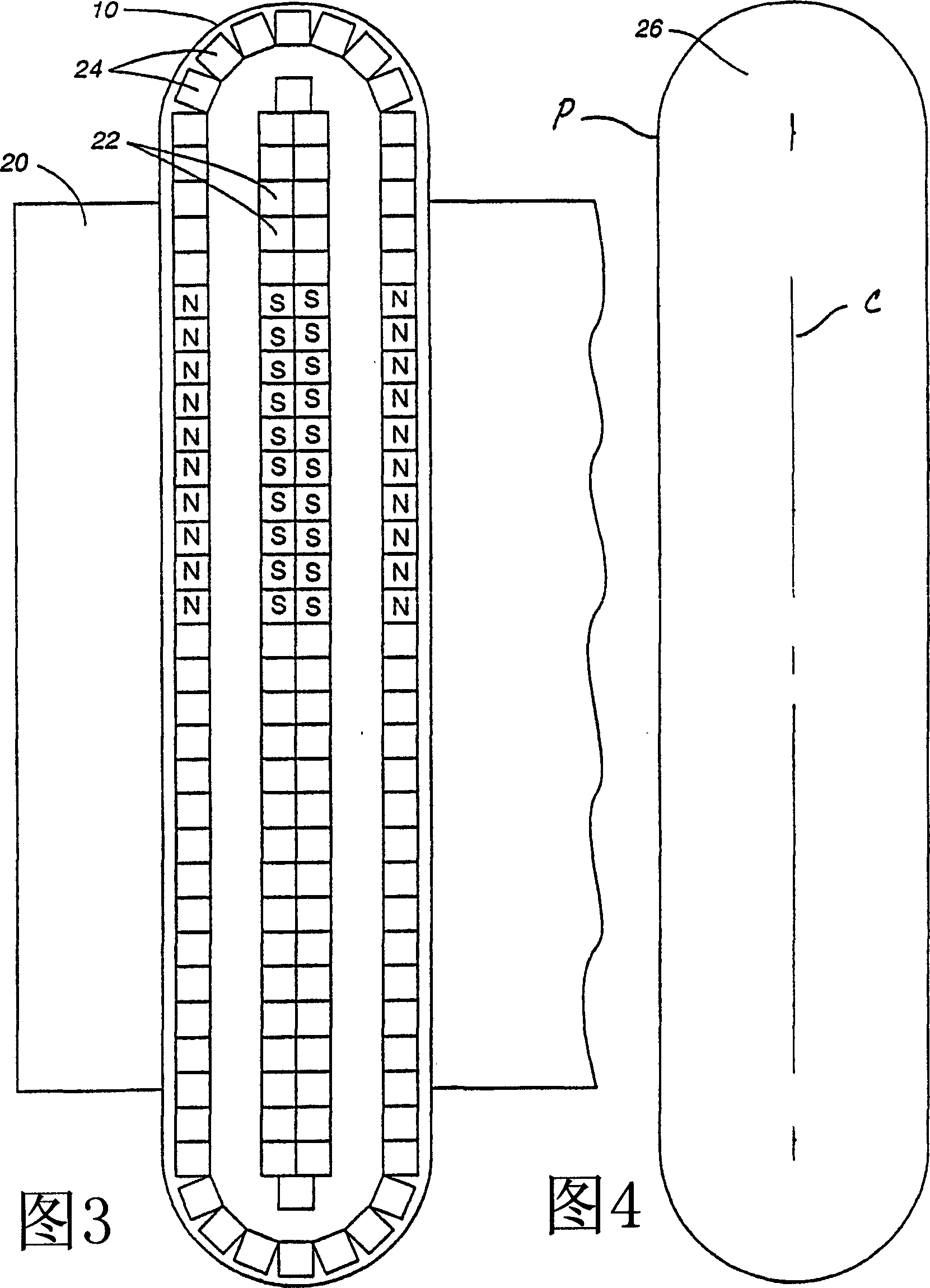
[0030] Figures 1 and 2 show a sputtering deposition chamber 8 with two inclined sputtering targets 10, 12, each of which has its own contaminant barrier shield 14, 16 according to the invention. The illustrated chamber is designed to accommodate large rectangular workpieces or substrates for manufacturing electronic video displays. This kind of substrate can currently be as large as 650mm×800mm (width×length), and it is expected that larger substrates will generally be used in the near future.

[0031] It is expensive and difficult to manufacture sputtering targets and magnets as large as such substrates. Therefore, the presently preferred embodiment of the present invention uses long and narrow rectangular targets 10, 12, each of which has a longer length than the substrate, but the width is much smaller than the width of the substrate. The carrier 18 slowly moves the substrate 20 horizontally through the target so that the material sputtered from the target covers the entire sub...


PUM


Abstract

A sputter deposition apparatus and method includes perimeter magnets oriented an angle relative to the plane of the sputter target, either by magnetizing or by physically orienting the magnets at the chosen angle. The resulting magnetic flux extends radially outward, away from the central axis of the target, toward and beyond the target perimeter. This causes the return path of the flux to pass over the target surface more parallel to the plane of its sputtering surface. This spreads sputter erosion over a greater area of the target surface and mitigates development of sputtering grooves. Since target erosion is more uniform, more target material is used for sputter deposition, deterring waste. Each target can be used longer before the target material is penetrated, resulting in fewer target replacement cycles for a given volume of workpiece coating, raising the deposition chamber capacity factor.

Description

[0001] This is a partial continuation of the pending application 09 / 429,762 on October 10, 1999. Technical field [0002] The present invention generally relates to equipment for sputtering deposition on electronic workpieces such as flat panel displays, and in particular, to a tilted sputtering target and shield for preventing contaminant particles from the target from falling on the workpiece on. More specifically, the present invention relates to the arrangement and orientation of accelerator magnets, which can improve the utilization efficiency of target materials and sputtering chambers. technical background [0003] Large flat panel displays and other electronic devices are usually manufactured through a series of process steps, in which process steps include the steps of depositing a continuous layer of material on a workpiece, such as a glass substrate, and then patterning. Some deposition steps are generally performed by sputter deposition, which is the deposition of sput...

Claims


Application Information

Patent Timeline
Patent Type & Authority Applications(China)
IPC IPC(8): C23C14/00C23C14/34C23C14/35C23C14/56H01J37/32H01J37/34H01L21/203H05H1/46
CPCH01J37/3408H01J37/3405H01J37/3447C23C14/56C23C14/352H01J37/34
Inventor A·霍索卡瓦R·穆拉普第
Owner APPLIED MATERIALS INC
Why Eureka
Try Eureka