Camera

A camera and viewfinder technology, applied in the field of cameras, can solve problems such as unfavorable camera miniaturization

Inactive Publication Date: 2004-09-01
CANON KK
View PDF1 Cites 5 Cited by
  • Summary
  • Abstract
  • Description
  • Claims
  • Application Information

AI Technical Summary

Problems solved by technology

Therefore, it is necessary to arrange other components of the camera (such as the battery chamber for loading the power battery, etc.) on the left side of the dotted line B, which is not conducive to the miniaturization of the camera.

Method used


Image

  • Camera
  • Camera
  • Camera

Examples


Embodiment Construction

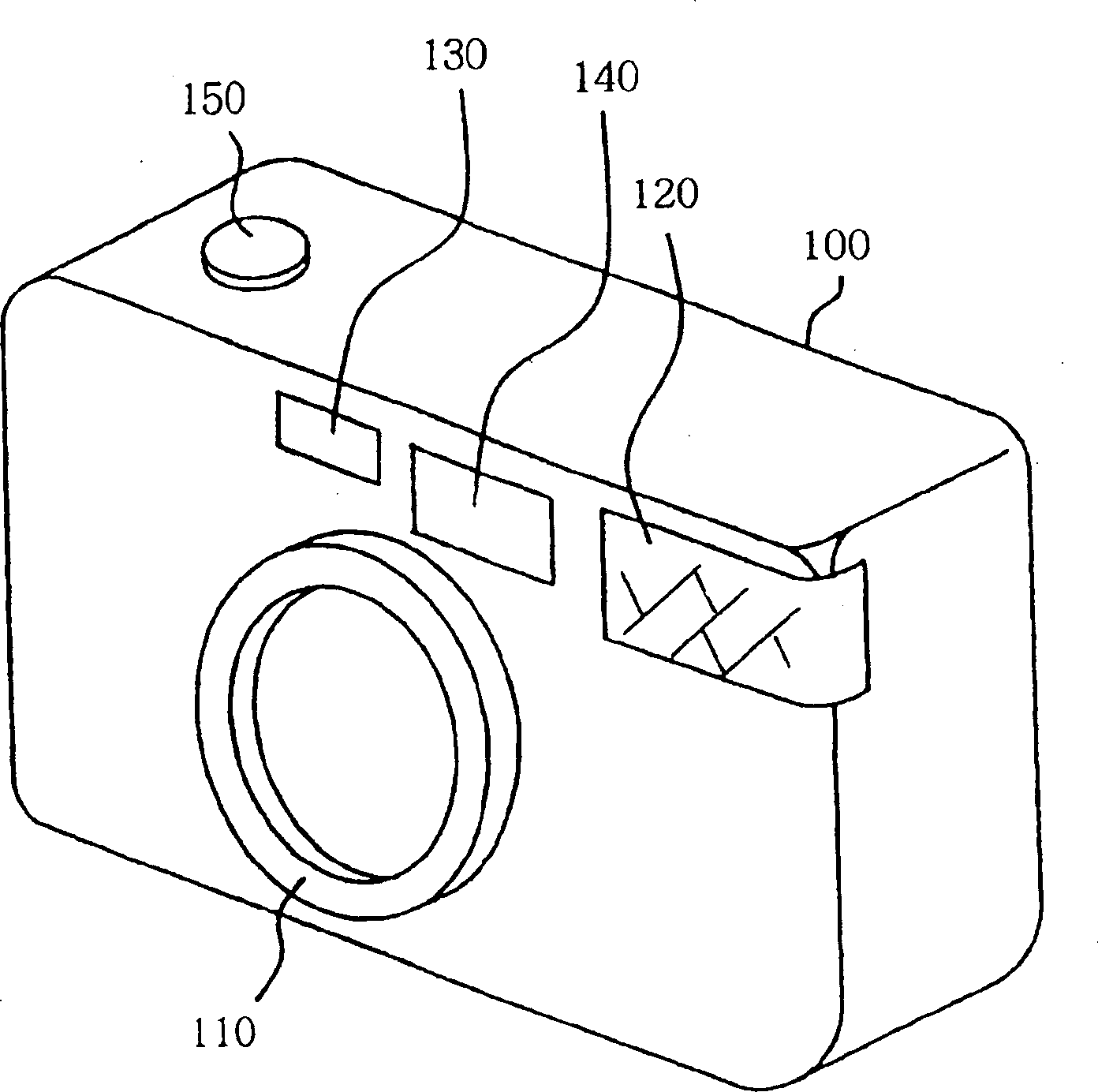
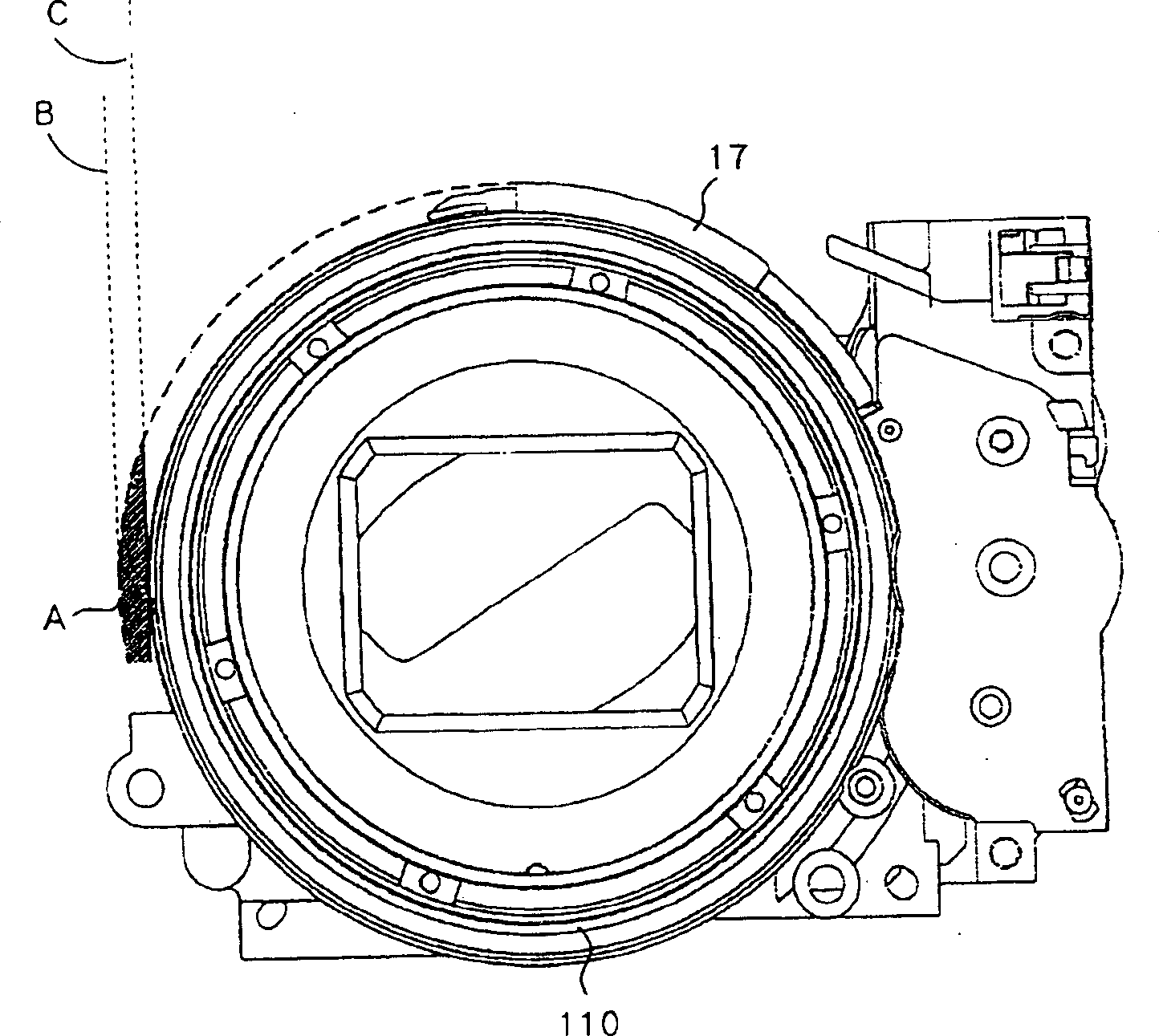
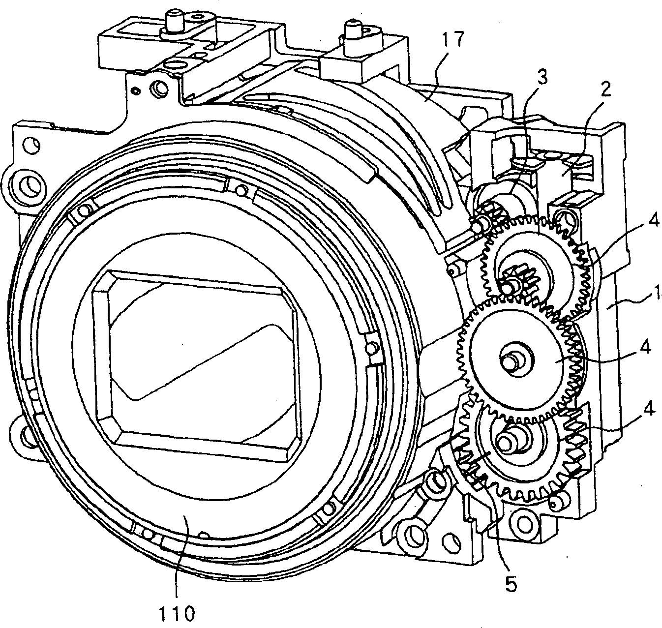
[0023] Hereinafter, a camera according to Embodiment 1 of the present invention will be described with reference to the drawings. here, figure 1 Shown is a camera of embodiment one of the present invention, figure 2 Shown is a lens barrel of a camera according to an embodiment of the present invention.

[0024] exist figure 1 Among them, 100 is a camera body, and a lens barrel 110 capable of zooming is provided at the front center of the camera body 100 . In addition, on the right side facing the front of the camera body 100, a light emitting window 120 constituting a flash that illuminates the subject with illumination light is provided, and a finder window 140 and a photometer are respectively provided on the left side of the light emitting window 120. window portion 130 .

[0025] In addition, a release button 150 is provided on the top of the camera body 100 for starting shooting preparations (focusing and photometry) and shooting (exposure to film, CCD, CMOS sensor...


PUM


Abstract

The present invention discloses a camera capable of reducing the size by reducing the range of movement of a view finder driving member which operates interlocked with an image-taking lens barrel. The camera includes an image-taking lens barrel which performs a operation in a collapse region and performs a zooming operation in an image-taking region, a view finder optical system including a movable lens unit and a view finder driving member having a cam which drives the movable lens unit. The image-taking lens barrel operates interlocked with the view finder driving member in the image-taking region and the interlock between the image-taking lens barrel and the view finder driving member is released in the collapse region.

Description

technical field [0001] The present invention relates to a camera that drives a viewfinder in conjunction with the movement of a lens barrel. Background technique [0002] Conventionally, a camera in which a viewfinder is driven in conjunction with the rotation of a rotating barrel constituting a lens barrel has been proposed (see Japanese Patent Laid-Open No. H09-211300 and Japanese Patent Laid-Open No. 2001-324749). Figure 10 with Figure 11 Shown is such a camera. [0003] In these figures, 60 is a rotating barrel constituting a lens barrel, and 170 is a viewfinder driving part. The viewfinder driving member 170 is disposed so as to be in contact with the rotating tube 60 rotating around the optical axis, and rotates together with the rotating tube 60 around the optical axis (in the direction opposite to the D direction) due to the contact of the rotating tube 60 . [0004] In addition, the viewfinder driving member 170 is biased in the direction opposite to the D direc...

Claims


Application Information

Patent Timeline
Patent Type & Authority Applications(China)
IPC IPC(8): G03B13/12G02B7/04G02B7/08G03B5/00G03B17/00G03B17/04
CPCG03B17/00
Inventor 永柄龙一
Owner CANON KK
Why Eureka
Try Eureka