Electric heating device with heating zones

An electric heating device and a heating device technology are applied to electric heating devices, heating elements, air heaters, etc., to achieve the effect of low manufacturing cost

Inactive Publication Date: 2004-09-01
CATEM
View PDF0 Cites 36 Cited by
  • Summary
  • Abstract
  • Description
  • Claims
  • Application Information

AI Technical Summary

Problems solved by technology

[0006] These conventional auxiliary electric heating elements and vehicle air conditioning units are disadvantageous because they cannot individually heat the corresponding "zones"

Method used


Image

  • Electric heating device with heating zones
  • Electric heating device with heating zones
  • Electric heating device with heating zones

Examples


Embodiment Construction

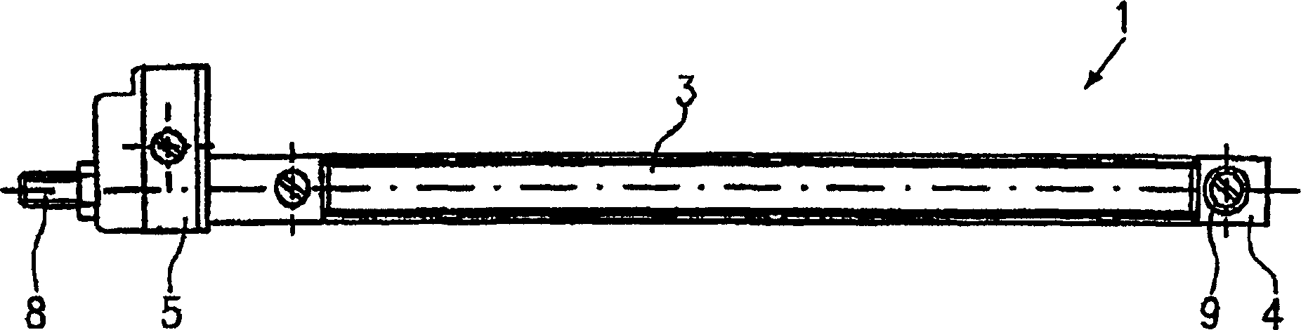
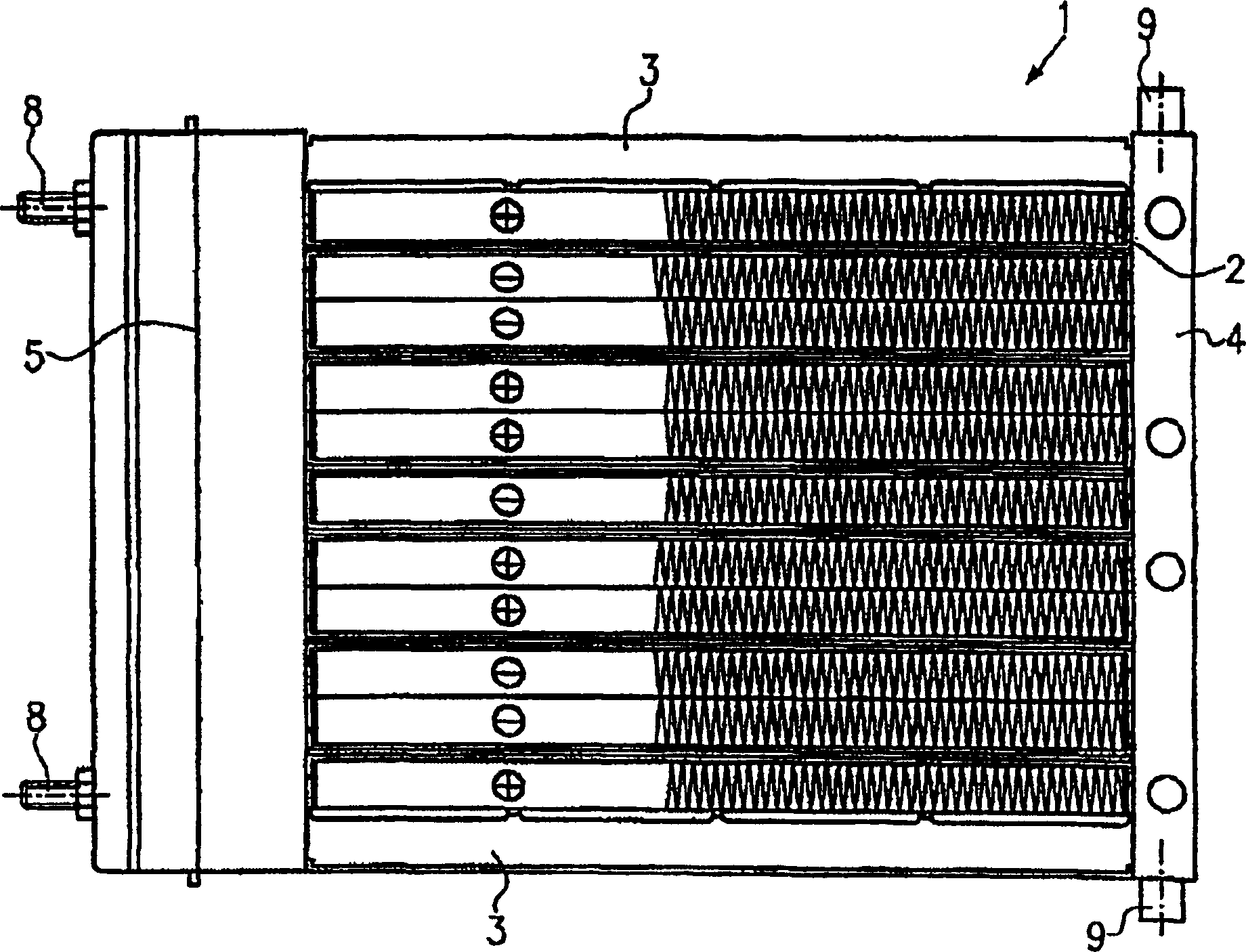
[0032] A structural design suitable for electric heating devices, in particular in motor vehicles, is shown in Figure 1a and Figure 1b middle. Figure 1a A side view is shown in , while Figure 1b It is the top view of the electric heating device. The electric heating device 1 is provided with a thermal recorder comprising a plurality of layered or laminated heating elements. Each heating element includes at least one resistive heating element and a heat sink element or thermally conductive sheet disposed adjacent thereto. The elements used as resistive heating elements are preferably PTC heating elements. The thermal recorder is held on a frame comprising opposed longitudinal bars 3 and lateral bars 4 and 5 arranged at right angles to these longitudinal bars 3 . The frame rods are made of metal or plastic material.

[0033] The longitudinal bars have essentially the same structural design. However, the opposite lateral bars 4 and 5 differ in that the lateral bar 5 is i...


PUM


Abstract

An electric heating device is adapted to be used in particular as an auxiliary electric heating for motor vehicles. The heating device comprises a plurality of PTC heating elements arranged in a plane of said heating device. The PTC heating elements are in electric contact with contact sheets for supplying current thereto and in thermal contact with radiator elements for transferring the heat produced to an air current to be heated. According to the present invention, the PTC heating elements arranged in this plane are adapted to be controlled separately in at least two groups.

Description

technical field [0001] The invention relates to an electric heating device for a motor vehicle. In particular, the invention relates to an electric heating device provided with a thermal register comprising individually controllable heating zones. Background technique [0002] In motor vehicles, in particular motor vehicles with consumption-optimized internal combustion engines, electric heating devices are used to heat the vehicle interior and the engine. However, such an electric heating device is also suitable for room air conditioning, for industrial equipment, household appliances, and the like. [0003] The improved efficiency of the consumption-optimized internal combustion engine results in a considerable reduction in the heating output in motor vehicles. When the engine is operating in the lower part load range and when the outside temperature is low, for example in winter, the engine cannot supply the heat required to heat the vehicle interior. In order to compe...

Claims


Application Information

Patent Timeline
Patent Type & Authority Applications(China)
IPC IPC(8): H05B3/02B60H1/03B60H1/22F24H3/04H05B3/03H05B3/06H05B3/10H05B3/14H05B3/50
CPCB60H2001/2287H05B3/50B60H2001/2237H05B3/14H05B2203/02F24H9/1872B60H1/2225F24H3/0429H05B3/10
Inventor F·伯伦德尔M·克劳斯M·尼德雷尔
Owner CATEM
Why Eureka
Try Eureka