
Hydraulic coal mine support for low-position roof blasting-down

A technology of hydraulic support and top coal caving, which is applied in the direction of mine roof supports, pillars/supports, mining equipment, etc., can solve the problems of unbalanced force on front and rear columns, achieve favorable intensive management, reduce center distance, and structure compact effect

Inactive Publication Date: 2004-09-08
YANKUANG GRP CO LTD
View PDF2 Cites 15 Cited by
  • Summary
  • Abstract
  • Description
  • Claims
  • Application Information

AI Technical Summary

Problems solved by technology

[0006] In order to overcome the shortcomings of the existing low-level top-coal caving hydraulic support, the present invention provides a new type of low-level top-coal caving hydraulic support, which can fundamentally eliminate the defect of unbalanced force on the front and rear columns and improve the mechanical characteristics of the support , Improve the adaptability of the top-coal caving support to the surrounding rock, improve the support effect of the fully mechanized caving face, adapt to the requirements of high-yield and high-efficiency top-coal caving mining, and make it easier to realize electro-hydraulic control and production automation

Method used


Image

  • Hydraulic coal mine support for low-position roof blasting-down
  • Hydraulic coal mine support for low-position roof blasting-down
  • Hydraulic coal mine support for low-position roof blasting-down

Examples


Embodiment 1

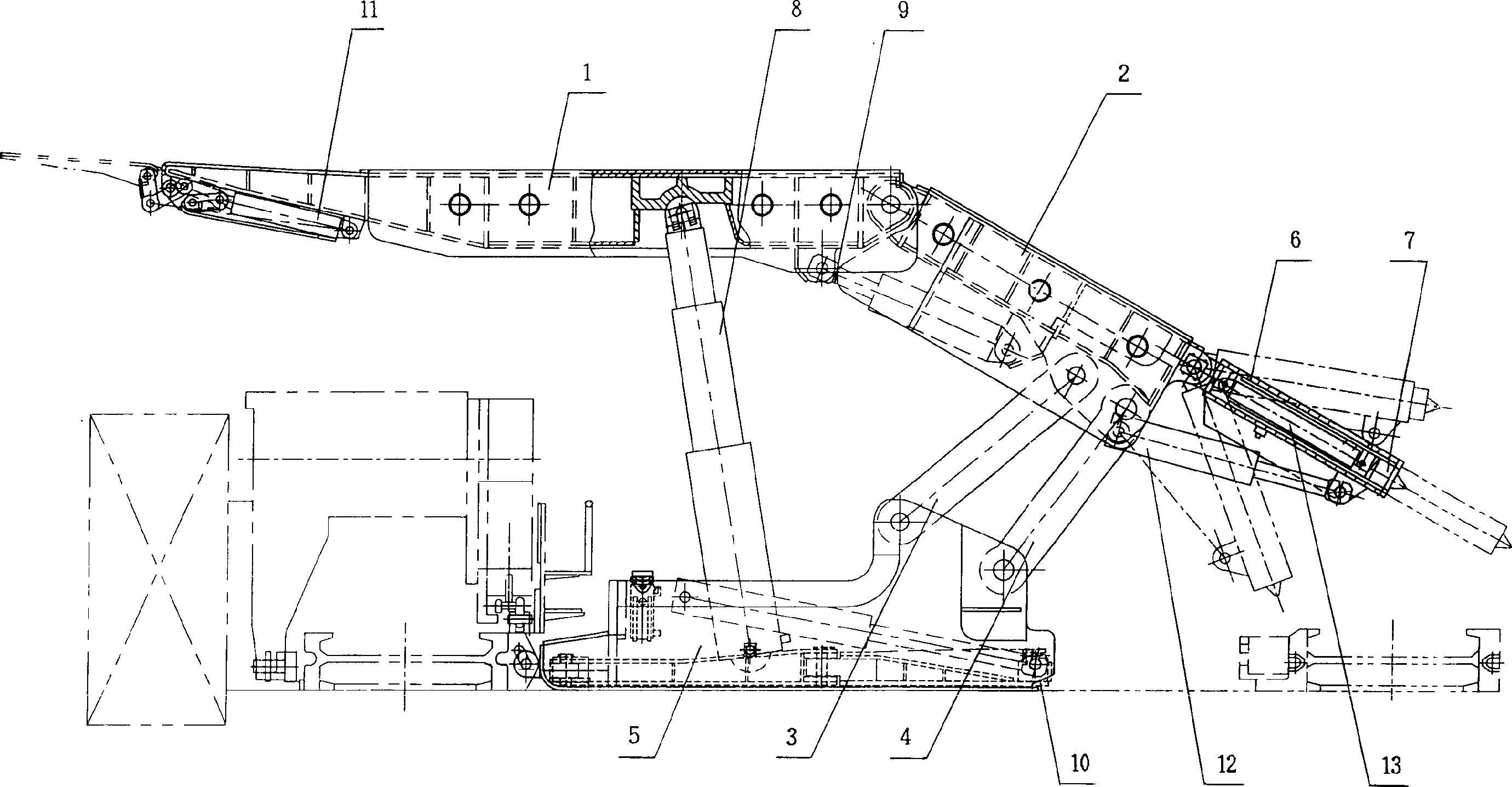
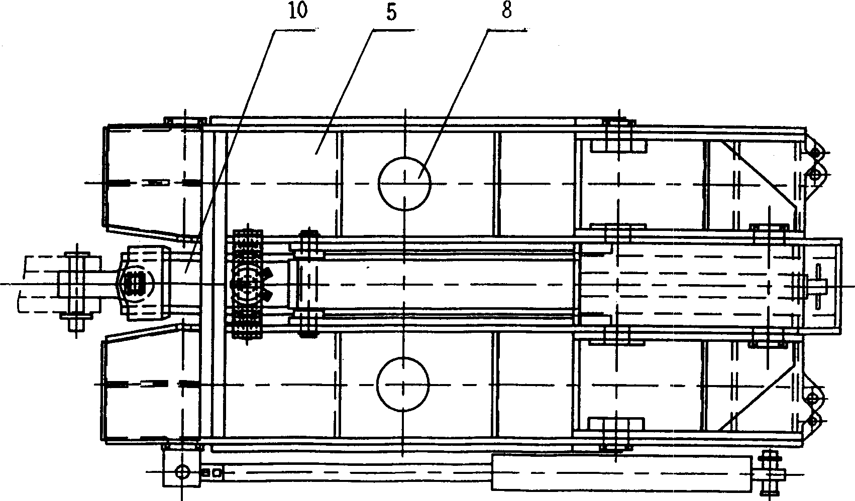
[0041] figure 1 The shown low-level top coal caving hydraulic support of the present invention mainly consists of a top beam (1), a shield beam (2), a front connecting rod (3), a rear connecting rod (4), a base (5), a column (8), Balance jack item (9), pushing mechanism (10), side protection device (11), and the tail beam (6) of coal discharge mechanism, inserting plate (7), tail beam jack (12) form.

[0042] The top beam (1) and the base (5) are hingedly supported by two columns (8), the rear end of the top beam (1) is hinged with the cover beam (2), and the top beam (1) and the cover beam (2) There are two balance jacks (9) hinged between the two below the hinge point, the rear end of the cover beam (2) is hinged with the tail beam (6) of the coal discharge mechanism, and the cover beam (2) and the tail beam (6) are hinged. ) has a tail boom jack (12) hinged between the two below the hinge point. The front connecting rod (3) and the rear connecting rod (4) are hinged betwe...

Embodiment 2

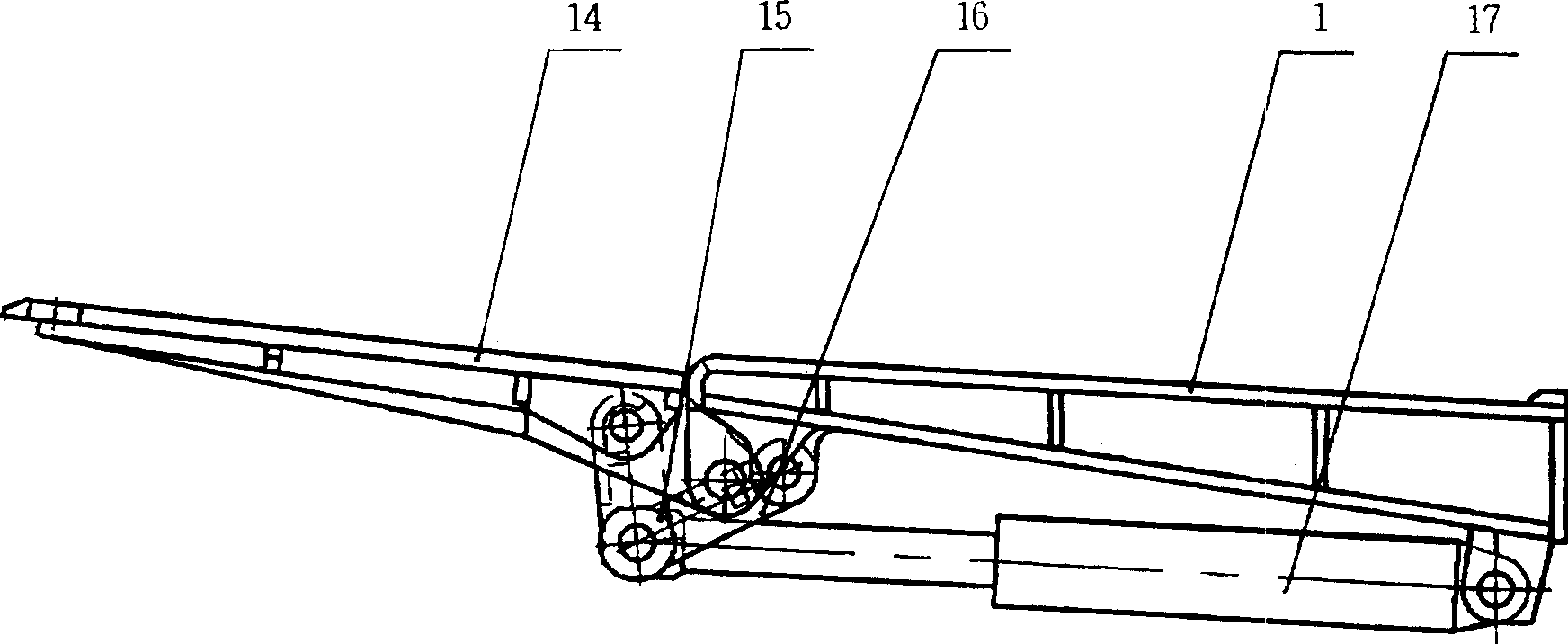
[0058] Figure 8 Another form of the present invention is shown, that is, the two-column shielding type low-level coal caving hydraulic support with a hinged top beam as the top beam. Hinged top beam, or section hinged top beam, is made of top beam (25), front beam (23), front beam jack (24). The front beam (23) is hinged at the front end of the top beam (25), and the front beam jack (24) is hinged between the top beam (25) and the front beam (23). Correspondingly, the side protection device (11) of its four-bar linkage mechanism should be hinged on the front beam (23), that is, the rear end of the side protection plate (17), the long rod (15), and the side protection jack (16) are hinged At the front end of the front beam (23). Apart from this, the rest of this example can be the same as that of Example 1.

[0059] In the above two embodiments: the overall roof beam structure is simple and reliable, and the supporting force at the front end of the roof beam is large; the s...


PUM


Abstract

The hydraulic coal mine support for low-position roof blasting-down consists of single row double uprights with top beam and pedestal hinged to ends, securing beam hinged to back of the top beam, coal blasting mechanism behind the securing beam, front link rod and back link rod hinged to between the pedestal and the securing beam, pedestal pushing mechanism, top beam protecting unit, balancing jack hinged to between the top beam and the securing beam, etc. The coal blasting mechanism consists of tail beam, board inserting jack, inserted board and tail beam jack. The hydraulic coal mine support is developed by synthesizing available supports, and has the advantages of homogeneous upright stress, compact structure, high support strength, high safety, etc.

Description

Technical field [0001] The invention relates to supporting equipment for underground coal mine back mining working faces, in particular to a low-position top-coal caving hydraulic support suitable for fully-mechanized top-coal caving working faces with a coal thickness greater than 5 meters and good top-coal caving performance. Background technique [0002] In the past, two-column shielded high-level coal caving hydraulic support was used. The support is a short top beam, a single hinge point stabilization mechanism, two columns supported on the cover beam, and the cover beam is a single-conveyor top-coal caving support with a skylight. It is the earliest top-coal caving support. disuse. [0003] At present, the top-coal caving hydraulic supports used in the fully mechanized top-coal caving face are all four-column support shielding supports. According to the form of the stabilizing mechanism, it can be divided into: forward four-link four-column top-coal caving support, r...

Claims


Application Information

Patent Timeline
IPC IPC(8): E21D15/48E21D23/04
Inventor 杨德玉金太黄福昌李政王国法邓新华张崇宏曾明胜
Owner YANKUANG GRP CO LTD
Learn More